
Floatation and ink removing machine

A deinking machine and flotation technology, applied in the field of papermaking machinery, can solve the problems of reduced pulp quality, increased operating costs, large driving force, etc., and achieve the effect of high pulp quality and thorough deinking

Inactive Publication Date: 2007-12-12
SHENZHEN DEWEI INTELLIGENT MFG TECH CO LTD
View PDF1 Cites 4 Cited by
  • Summary
  • Abstract
  • Description
  • Claims
  • Application Information

AI Technical Summary

Problems solved by technology

[0004] The disadvantages of the above-mentioned flotation cell are: 1. Because the flotation cell is a large airtight container with complex structure and high failure rate, it is very difficult to maintain the internal operating parts; 2. During the working process of the flotation cell, large driving force, increasing operating costs
[0006] However, in the two technical schemes described in this background technology, the size and quantity of the flotation bubble diameters are random, and the distribution of the flotation bubble diameter and quantity is related to the size and quantity of the ink particle diameters contained in the flotation pulp, There is no necessary corresponding matching relationship, so some ink particles cannot be completely taken away by the flotation bubbles, resulting in incomplete deinking and reduced pulp quality

Method used


Image

  • Floatation and ink removing machine
  • Floatation and ink removing machine
  • Floatation and ink removing machine

Examples


Embodiment 1

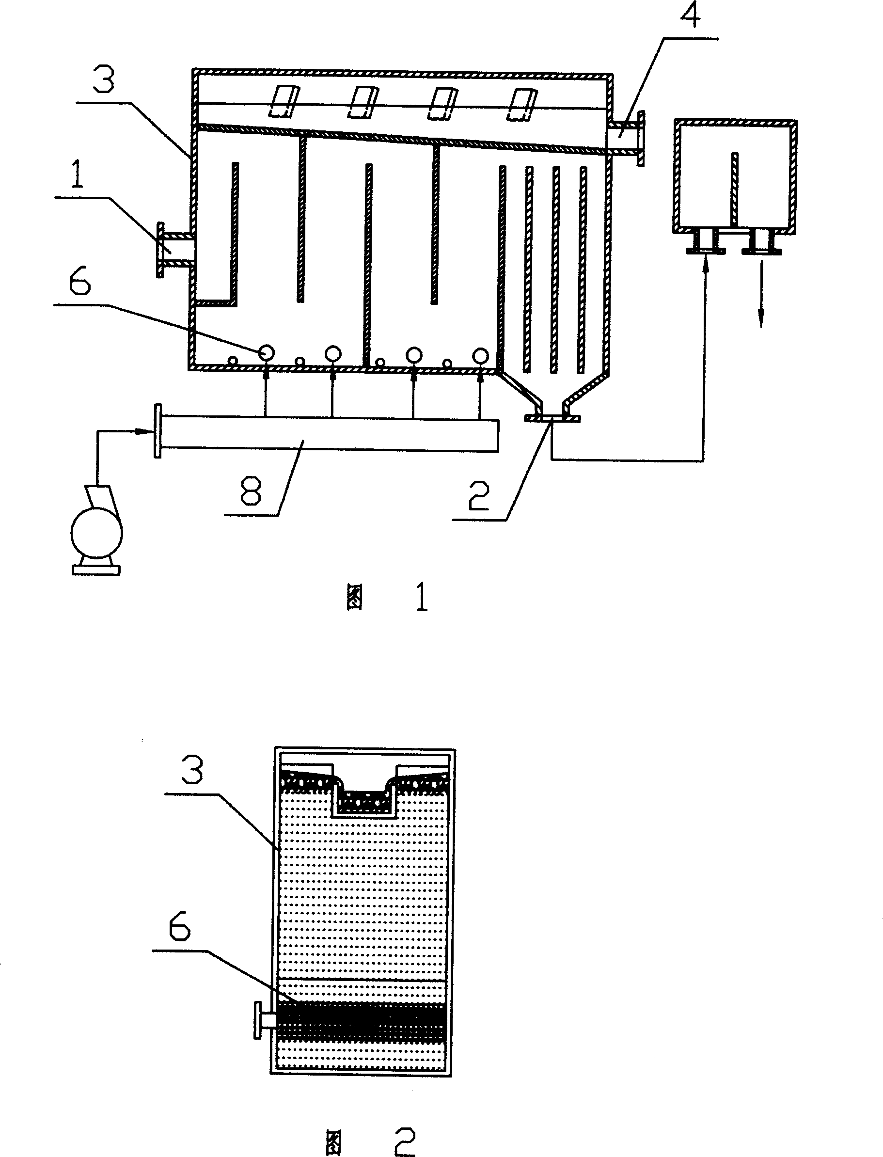
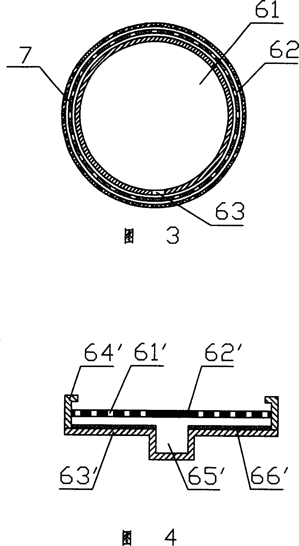
[0022] Embodiment 1: As shown in Figure 1, Figure 2, and Figure 3, the flotation deinking machine includes a deinking machine housing 3, a liquid inlet 1 provided on one side of the deinking machine housing 3 and The liquid outlet 2 on the other side of the bottom of the machine housing 3, the ink collecting device located on the upper part of the cavity of the deinking machine housing 3 and the slag outlet 4 connected with the ink collecting device, the deinking machine housing 3 A number of microporous aeration devices 6 that can send flotation bubbles to the liquid in the deinking machine housing are installed at the bottom of the cavity, and an air inlet pipe 8 connected to the microporous aeration device 6, the plurality of microporous aeration devices 6 is equipped with air holes that can generate bubbles of different diameters.

[0023] In this embodiment, the diameters of the air holes of the single microporous aeration device 6 are the same, that is, each microporous aera...

Embodiment 2

[0026] Embodiment 2: As shown in Fig. 1, Fig. 2 and Fig. 4, this embodiment is basically the same as the first embodiment, and the difference lies in the structure of the microporous aeration device 6.

[0027] In FIG. 4, the microporous aeration device 6 includes an air distribution plate 62' provided with a plurality of air outlet pores 61', and a bottom plate 63 located under the air distribution plate 62' and capable of blocking the air outlet pores 61' of the air distribution plate ', the bottom plate 63' is provided with an air distribution plate movement limiting device 64', the bottom plate is also provided with a recessed air inlet groove 65', and the corresponding air distribution plate above the air inlet groove 65' does not Equipped with air outlet holes. A sealing rubber gasket 66' is provided between the air distribution plate 62' and the bottom plate 63'; the sealing rubber gasket 66' is fixed on the bottom plate 63'. The working principle is: when not working, the ...


PUM


Abstract

The invention discloses a flotation deinking machine, it includes deinking machine shell, liquid feeding mouth installed on one side of deinking machine shell and liquid discharging mouth installed on another side of deinking machine shell, ink-gathering device installed in the upper of the cavity of deinking machine shell and the slag hole connected with the ink-gathering device, the bottom of said cavity of deinking machine shell is equipped with several micropore aeration device which can transmit flotation foam to the liquid in deinking machine shell, and air intake pipes connected with micropore aeration device, said several micropore aeration device is equipped with foam-generating hole which can generate foams in different diameter; due to the distribution of the diameter and the amount of flotation foam are matched with the size and the amount of the ink particles contained in the flotation pulp, ink particles in different diameters can be bright away by the flotation foam, the deinking is more thorough and the pulp quality is higher.

Description

Technical field [0001] The invention relates to a papermaking machine, in particular to a machine designed for deinking waste paper pulp or papermaking wastewater. Background technique [0002] In the waste paper processing technology, the recovered waste paper is crushed, decomposed, and added with medicine to separate the printing ink from the fiber in the waste paper to form an undeinked pulp suspension, that is, mortar. Then the flotation process is used to deink the waste paper pulp to improve the whiteness of the waste paper pulp. As we all know, air bubbles play an irreplaceable role in flotation. The number, size and stability of bubbles all affect the flotation effect. The ratio between the size of the air bubble diameter and the size of the ink particles is an extremely important factor affecting the flotation effect. Large ink particles need large bubbles to adsorb it, and small ink particles need small bubbles to adsorb; after testing, The ratio of the air bubble diam...

Claims


Application Information

Patent Timeline
IPC IPC(8): D21C5/02D21C9/00
CPCY02W30/64
Inventor 李风宁
Owner SHENZHEN DEWEI INTELLIGENT MFG TECH CO LTD
Learn More