
Liquid crystal display

A technology of liquid crystal display and liquid crystal layer, applied in static indicators and other directions, can solve problems such as inability to observe, achieve the effects of increasing convenience, improving pass rate, and overcoming accumulation

Active Publication Date: 2007-11-28
WUHAN CHINA STAR OPTOELECTRONICS TECH CO LTD
View PDF1 Cites 10 Cited by
  • Summary
  • Abstract
  • Description
  • Claims
  • Application Information

AI Technical Summary

Problems solved by technology

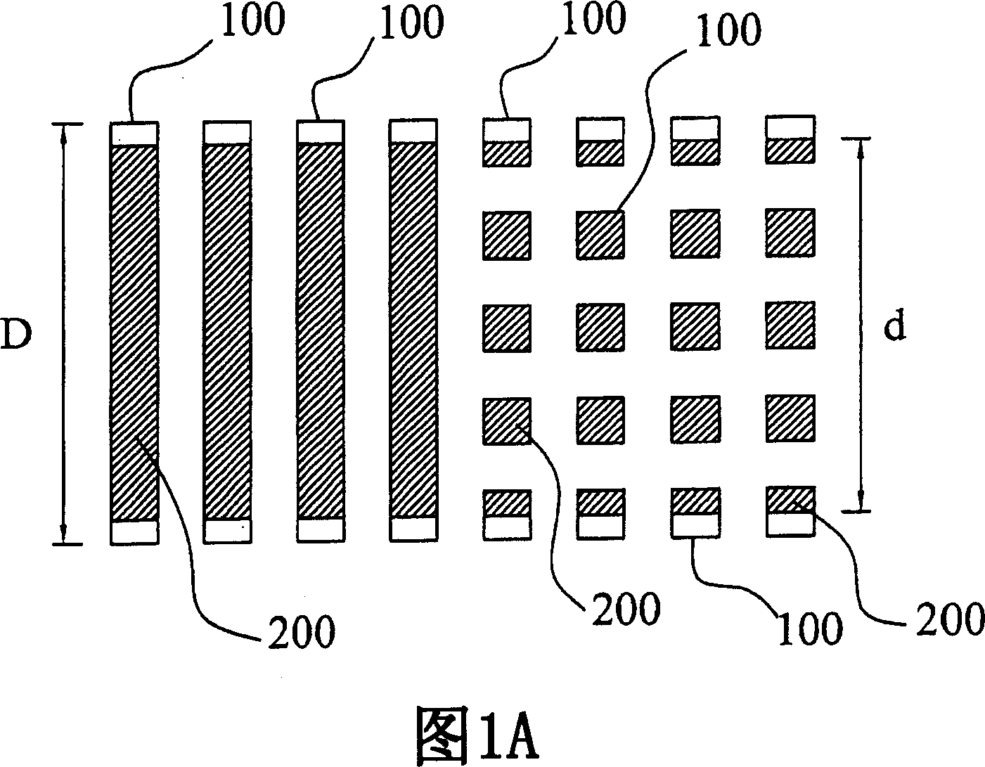
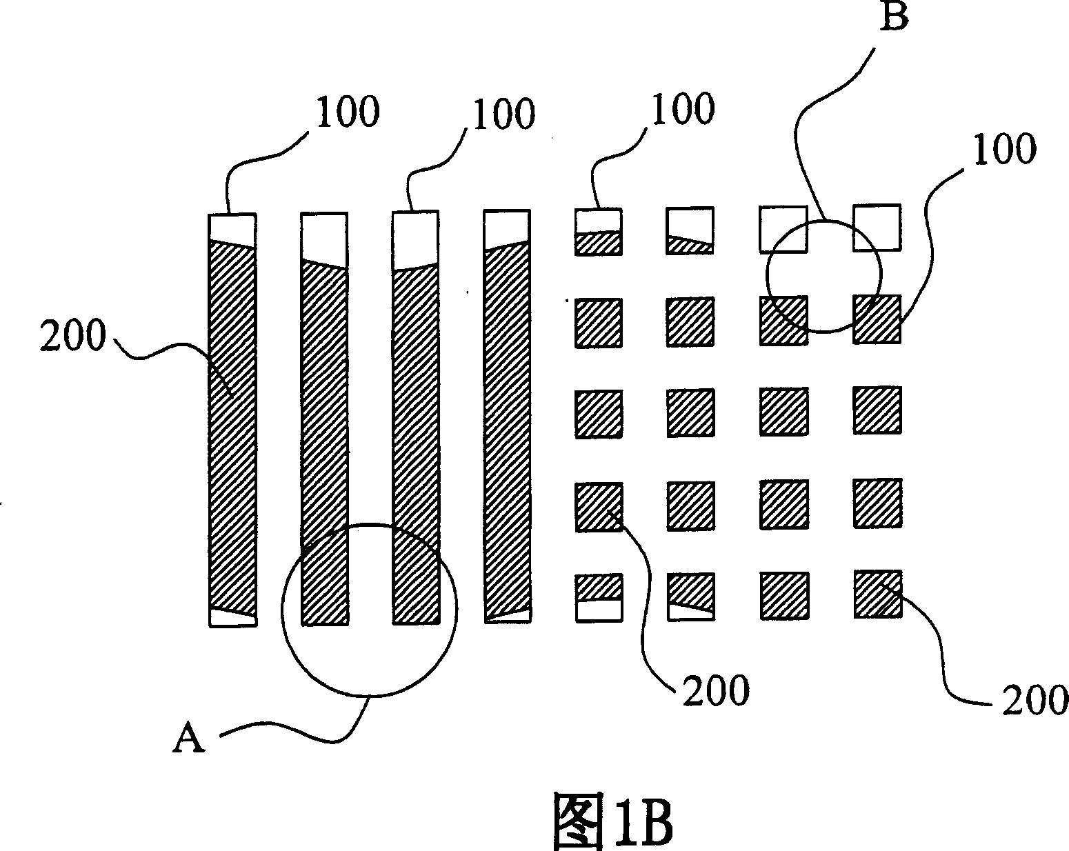
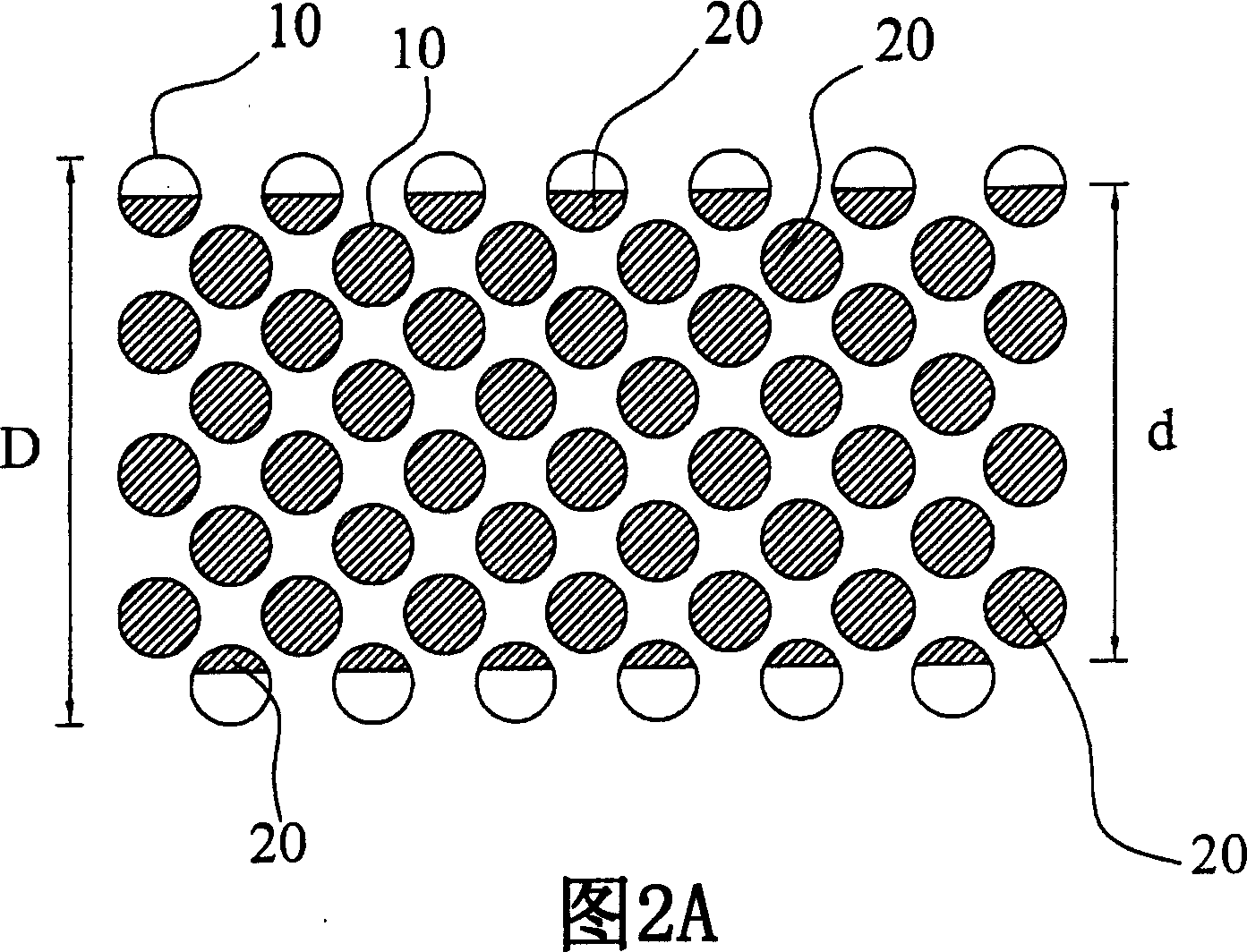
[0008] In order to improve the problem that the frame glue is applied between the window and the window of the frame glue observation window and sometimes cannot be observed, one of the purposes of the present invention is to provide a liquid crystal display, which reduces the monitoring time by setting the positions of the frame glue observation window in a staggered manner. blind spot

Method used


Image

  • Liquid crystal display
  • Liquid crystal display
  • Liquid crystal display

Examples


Embodiment Construction

[0039] FIG. 3A is a schematic plan view of a liquid crystal display according to an embodiment of the present invention. Fig. 3B is an enlarged cross-sectional schematic diagram according to the section line A-A' in Fig. 3A. In this embodiment, the liquid crystal display comprises a first substrate 30, and this first substrate 30 has a black matrix layer 32, and a second substrate 40 is arranged on the relative position of the first substrate, and the second substrate has a thin film transistor (on the figure not shown), a liquid crystal layer 52 is filled between the first substrate 30 and the second substrate 40 , and the first substrate 30 and the second substrate 40 are bonded by the sealant 20 . The sealant 20 is coated on the non-display area and surrounds the display area 50 of the liquid crystal display panel. There is a liquid crystal layer 52 in the liquid crystal display area. The sealant 20 will leave a liquid crystal injection port in a specific area for subsequen...


PUM


Abstract

The invention relates to a LCD, comprising a first base plate and a second base plate, a liquid crystal layer set between the first base plate and the second base plate, plural frame-glue observing windows set on the second base plate, which are the closed pattern of smooth curve, and frame glue covering partial frame-glue observing windows and round the liquid crystal layer and bonding the first base plate and the second base plate. The frame-glue observing windows of invention can avoid uneven gap and increase convenience for coating state of observing frame glue.

Description

technical field [0001] The invention relates to a liquid crystal display, in particular to a liquid crystal display for uniform coating of frame glue. Background technique [0002] In the manufacturing process of Thin Film Transistor-Liquid Crystal Display (TFT-LCD), the control of sealing width and cell gap has a great influence on the final product quality. [0003] The frame glue is around the panel to bond the upper and lower glass substrates. Generally, there will be some spacers mixed in the frame rubber material, mainly to provide support for the upper and lower layers of glass. Since the spacers are granular, when the alignment is pressed, once the spacers gather, it is easy to cause uneven gaps. , the uneven gap will lead to uneven electric field distribution, thus affecting the gray level (gray level) performance of the liquid crystal. [0004] If the line width of the frame glue is too thin, it may cause poor exhaust procedures in the subsequent alignment lamina...

Claims


Application Information

Patent Timeline
Patent Type & Authority Applications(China)
IPC IPC(8): G02F1/133
Inventor 陈晓芬林振吉林泓铮
Owner WUHAN CHINA STAR OPTOELECTRONICS TECH CO LTD
Learn More