Electrochemical depositer with inductive anode

A deposition device and electrochemical technology, applied in the direction of electroforming, electrolysis process, etc., can solve the problems of poor localization of local electrochemical deposition and low processing accuracy

Inactive Publication Date: 2007-11-21
NANJING UNIV OF AERONAUTICS & ASTRONAUTICS
View PDF0 Cites 4 Cited by
  • Summary
  • Abstract
  • Description
  • Claims
  • Application Information

AI Technical Summary

Problems solved by technology

[0005] The purpose of the present invention is to provide an electrochemical deposition device using an induced ano

Method used


Image

  • Electrochemical depositer with inductive anode
  • Electrochemical depositer with inductive anode

Examples


Embodiment Construction

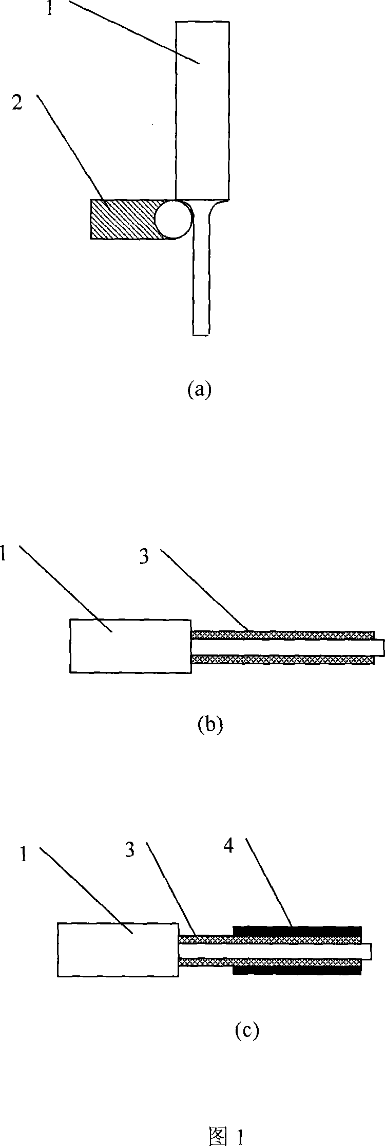
[0012] Below in conjunction with Fig. 1, Fig. 2 concretely illustrate the implementation of the present invention -- "using the electrochemical deposition device of induced anode".

[0013] As shown in Figure 1: the local electrochemical deposition induction anode is composed of three layers of materials: a central platinum wire 1, an insulating layer 3 and an outer conductive layer 4.

[0014] The manufacturing method of this induced anode is:

[0015] (1) As shown in Figure 1(a), use a wire electrode spark grinding (WEDG) device 2 to process a platinum wire 1 with a diameter of tens to hundreds of microns, and keep a larger diameter at one end for easy assembly. Clamp, the diameter of the other end depends on the size requirements of the processed parts.

[0016] (2) As shown in Fig. 1(b), insulate or coat the side wall of the small end of the platinum wire 1. The insulating material can be Teflon, plexiglass, epoxy resin and the like. When insulating, the end of the plati...


PUM


Abstract

An electrochemical depositor by inducing anode consists of centering platinum wire(1), insulating layer(3) and conducting layer(4) of external layer. Platinum wire(1) is connected with anode of power supply, conducting layer and cathode are connected with negative polar. Conducting layer and cathode same potential absorb electric-field emitted from edge of platinum wire end, decrease covering zone on cathode surface of electric field and improve depositing locality and precision by inducing anode local electrochemical deposition.

Description

technical field [0001] The electrochemical deposition device adopting the induced anode of the present invention belongs to the field of microfabrication. Background technique [0002] Electroforming is a special processing technology based on cathodic electrodeposition of metal ions to manufacture metal components. Electroforming parts are "stacked" by atoms and have high replication accuracy and repeatability. They are used in aviation, aerospace, weaponry, etc. obtained a wide range of applications. Especially since the 20th century, with the development of industrial products represented by micro-electromechanical systems (MEMS, Micro ElectroMechanical System) towards miniaturization, refinement, and intelligence, micro-electroforming, an important member of the micro-fabrication technology group , showing its super micro-processing ability, combined with other advanced science and technology, the electroforming technology has been rejuvenated, and it has become one of ...

Claims


Application Information

Patent Timeline
IPC IPC(8): C25D1/00
Inventor 朱荻曾永彬曲宁松
Owner NANJING UNIV OF AERONAUTICS & ASTRONAUTICS
Why Eureka
Try Eureka