Double-corner charge built-in filter cloth and filter plate and charging liquid-spraying mode
An embedded and feeding technology, which is applied in separation methods, filtration separation, chemical instruments and methods, etc., can solve the problems of many pipelines and valves, low product yield, high production cost, etc., and achieve the reduction of pipelines and valves , high yield and low production cost
- Summary
- Abstract
- Description
- Claims
- Application Information
AI Technical Summary
Problems solved by technology
Method used
Image
Examples
Embodiment 1
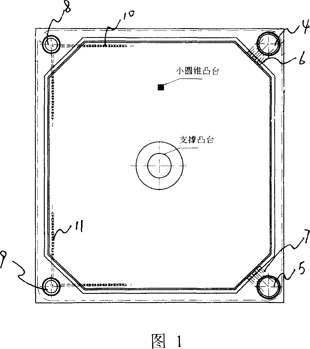
[0016] Embodiment 1: with reference to accompanying drawing 1. The double-angle feeding embedded filter cloth filter plate includes diaphragms 1 and 2 and a lining plate 3. Its manufacturing process belongs to the prior art and will not be described here. The feed through holes 4 and 5 are located at the double corners of the filter cloth filter plate, the feed branch holes 6 and 7 are located above the filter cloth and communicate with the feed through holes 4 and 5, and the feed branch holes 6 and 7 are composed of 2 or 2 The above feed branch holes are formed; the liquid outlet holes 8 and 9 are located at the double corners of the filter cloth filter plate and are opposite to the feed hole 4 and 5 respectively, and the liquid outlet holes 10 and 11 are located on the back of the filter cloth and communicate with the outlet. The holes 8 and 9 are connected, and the liquid outlet branch holes 10 and 11 are composed of 2 or more liquid outlet branch holes.
Embodiment 2
[0017] Embodiment 2: with reference to accompanying drawing 1~8. On the basis of Example 1, the way of feeding and discharging the embedded filter cloth filter plate with double-angle feeding is to feed the material from the lower corner first, then pass through the compact wallboard, and enter the upper corner reversely through the transition plate through the trough The feed hole finally enters the thrust wallboard, and the material enters the filter cavity formed by the filter cloth filter plate and the filter cloth filter plate through the feed through hole and the feed branch hole, and the material is filtered by the filter cloth on the filter cloth filter plate , the filtrate is discharged through the outlet branch hole and the outlet through hole on the back of the filter cloth.
Embodiment 3
[0018] Embodiment 3: On the basis of Embodiment 2, the feed holes 4 and 5 in the thrust wallboard are closed holes and are located at the double corners of the filter cloth filter plate, and the feed branch holes 6 and 7 are located above the filter cloth and connected to the inlet The material holes 4 and 5 are connected, and the feed hole located at the corner of the thrust wall plate has an exhaust through hole 12; the liquid outlet holes 8 and 9 are closed holes and are located at the double corners of the filter cloth filter plate, and the liquid outlet branch holes 10 and 11 is located on the back of the filter cloth and communicates with the outlet holes 8 and 9.
PUM
 Abstract
Description
Claims
Application Information
 - R&D Engineer
- R&D Manager
- IP Professional
- Industry Leading Data Capabilities
- Powerful AI technology
- Patent DNA Extraction
Browse by: Latest US Patents, China's latest patents, Technical Efficacy Thesaurus, Application Domain, Technology Topic, Popular Technical Reports.
© 2024 PatSnap. All rights reserved.Legal|Privacy policy|Modern Slavery Act Transparency Statement|Sitemap|About US| Contact US: help@patsnap.com


