Dynamically synchronizing a processor clock with the leading edge of a bus clock

A clock system and clock technology, applied in the direction of generating/distributing signals, can solve the problems of incorrect synchronization of bus and processor clock, misalignment of bus and processor clock, etc.

Active Publication Date: 2007-10-31
VIA TECH INC
View PDF0 Cites 10 Cited by
  • Summary
  • Abstract
  • Description
  • Claims
  • Application Information

AI Technical Summary

Problems solved by technology

As mentioned earlier, this technique of using a central clock control circuit has the disadvantage of misaligning the bus and processor clocks when the control signal is at the terminal node, resulting in the inability to properly synchronize the bus and processor clocks, so it needs to be done manually Adjustments to remove errors

Method used


Image

  • Dynamically synchronizing a processor clock with the leading edge of a bus clock
  • Dynamically synchronizing a processor clock with the leading edge of a bus clock
  • Dynamically synchronizing a processor clock with the leading edge of a bus clock

Examples


Embodiment Construction

[0088] Some embodiments of the present invention are described in detail as follows. However, the invention can be practiced broadly in other embodiments than those described in detail, and the scope of the invention should not be limited except by the claims hereof. Furthermore, in this specification, different parts of each component are not drawn to scale. Certain dimensions have been exaggerated compared to other relevant dimensions to provide a clearer description and understanding of the invention.

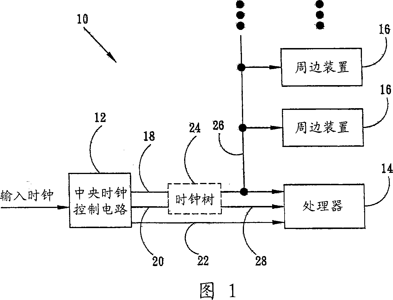
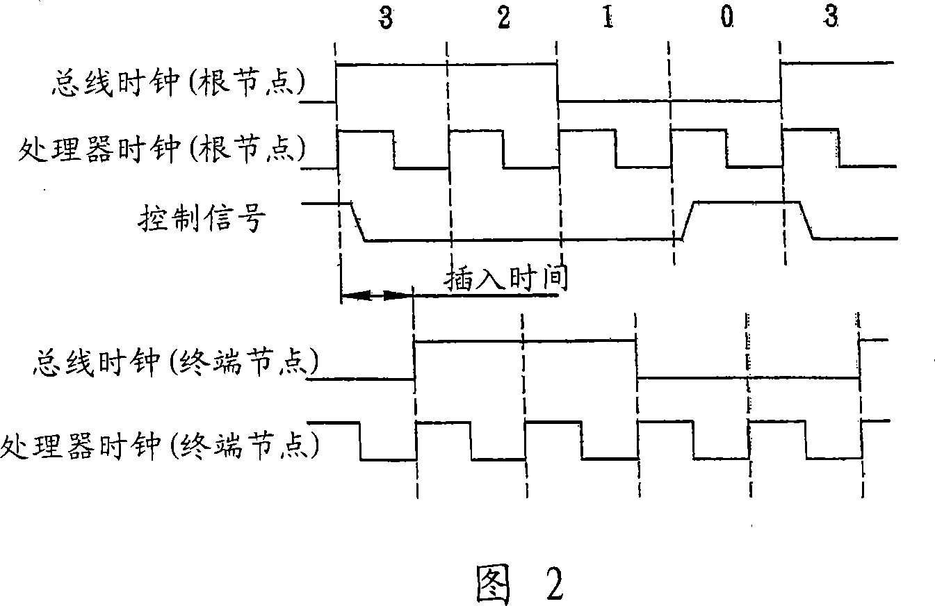
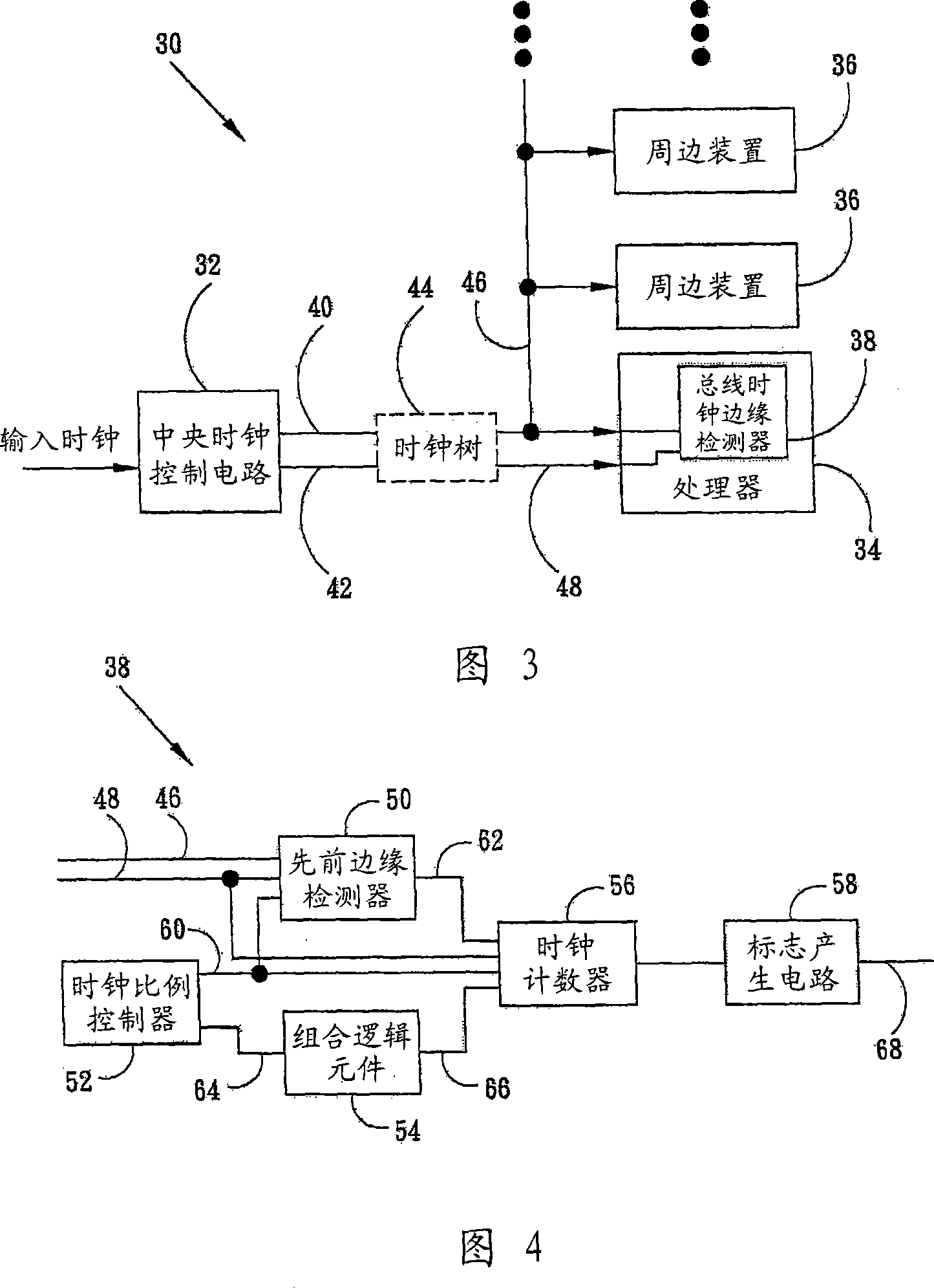
[0089] Since the central clock control circuit is used to generate control signals in the prior art, the bus clock inserted into the time delay and the processor clock signal cannot be aligned, resulting in timing problems, and chip designers need to manually design delay circuits to remove control signal error. The present invention uses a logic circuit to generate a flag signal, which is similar in concept to a control signal; however, the flag signal is only locally gen...


PUM


Abstract

Systems and methods for detecting a leading edge of a bus clock signal are disclosed herein. The detecting system includes a device for providing a bus clock and a processor clock, in which the processor clock is an integer multiple of the bus clock. The device for providing the clocks, however, does not provide a control signal that indicates the location of an edge of the bus clock. The system further includes a clock tree configured to distribute the bus clock and processor clock to multiple destinations, whereby the destinations receive the bus clock and processor clock delayed by an insertion time of the clock tree. The system also includes a processor having a device for detecting the leading edge of the bus clock delayed by the insertion time. Furthermore, a method is disclosed herein. The method includes generating a bus clock and a processor clock without a corresponding control signal, receiving an insertion-delayed version of the bus clock and processor clock, and processing the insertion-delayed bus clock and processor clock to generate a flag signal that indicates the location of a leading edge of the insertion-delayed bus clock.

Description

technical field [0001] The present invention relates to a processor or a microprocessor in a computer system or a system-on-chip (SOC) device, in particular to a circuit combined with a processor for detecting the leading edge of a bus clock (leading edge) to dynamically synchronize the higher frequency processor clock with the lower frequency bus clock. Background technique [0002] Computer systems usually advertise product performance based on various characteristics of the processor, especially the processor's internal clock. In general, the frequency of the processor clock will be many times higher than the frequency of the bus clock, so although the processor can usually operate at the fast clock speed as advertised in the data sheet, many processor clocks have no direct impact on the bus and peripherals. Too fast for the device. Therefore, these processors can only communicate with peripheral devices at lower interface bus speeds. Even in system-on-chip (SOC) device...

Claims


Application Information

Patent Timeline
IPC IPC(8): G06F1/12
CPCG06F1/10G06F1/12
Inventor 威廉V·米勒
Owner VIA TECH INC
Why Eureka
Try Eureka