Draw forming method and device

A fixture device and position-limiting technology, which is applied in the field of drawing forming and its devices, can solve the problems of large deviations in forming dimensions and achieve the effect of reducing deviations

Inactive Publication Date: 2007-10-24
HONDA MOTOR CO LTD
View PDF0 Cites 11 Cited by
  • Summary
  • Abstract
  • Description
  • Claims
  • Application Information

AI Technical Summary

Problems solved by technology

As a result, the variation in molded dimensions may become large

Method used


Image

  • Draw forming method and device
  • Draw forming method and device
  • Draw forming method and device

Examples


Embodiment Construction

[0028] Below, several embodiments of the present invention will be described in detail based on the drawings.

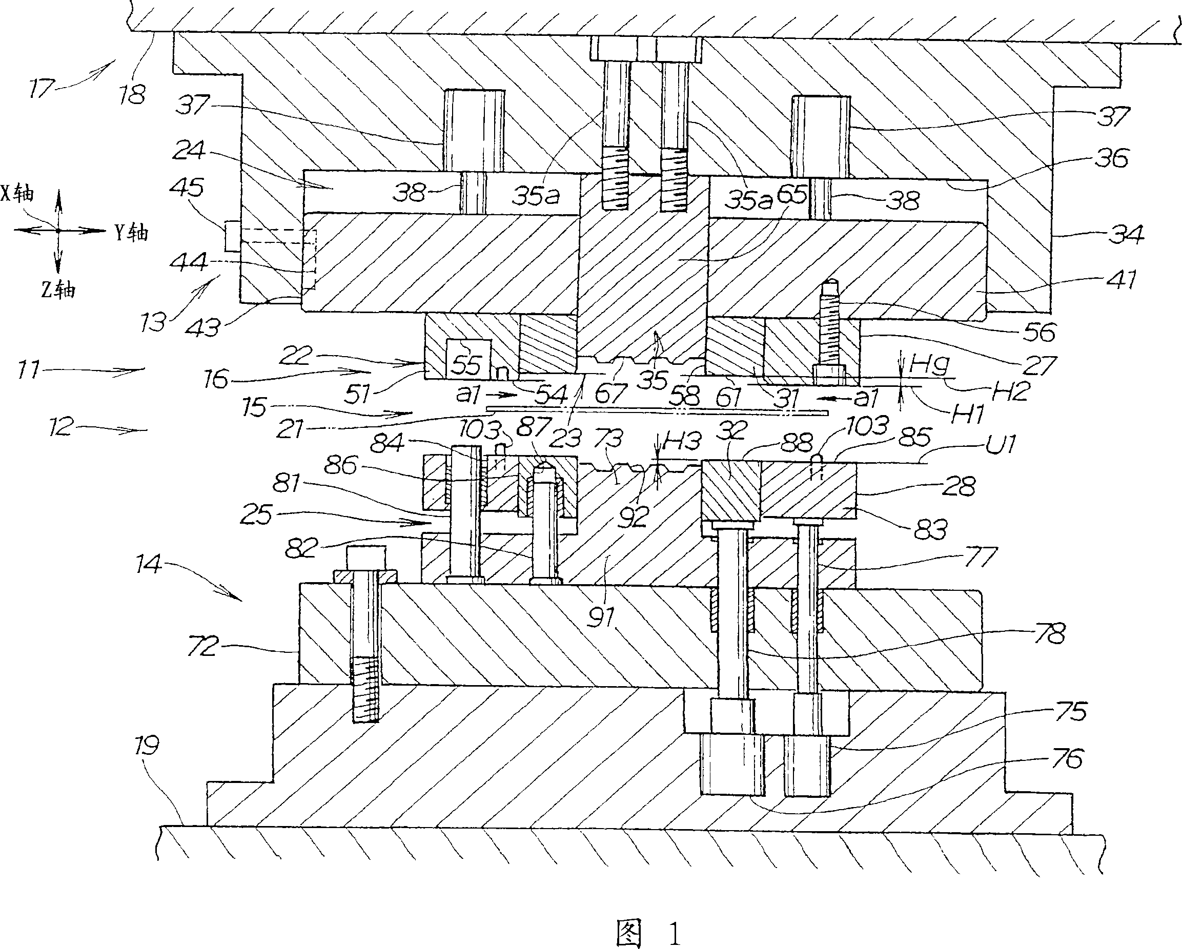
[0029] In FIG. 1 , X is the horizontal axis in the longitudinal direction of the blank 15 , Y is the horizontal axis perpendicular to X, and Z is the vertical axis perpendicular to X and Y.

[0030] The drawing forming device 11 of the first embodiment shown in Fig. 1 is made of mold 12 and blank holder 16, wherein, mold 12 is made of upper mold 13 and lower mold 14, and blank holder 16 is arranged on this mold 12 and Press blank 15. The upper die 13 is installed on the ram 18 of the press 17 . The lower die 14 is mounted on a pedestal 19 of a press 17 . The drawing apparatus 11 described above performs drawing processing.

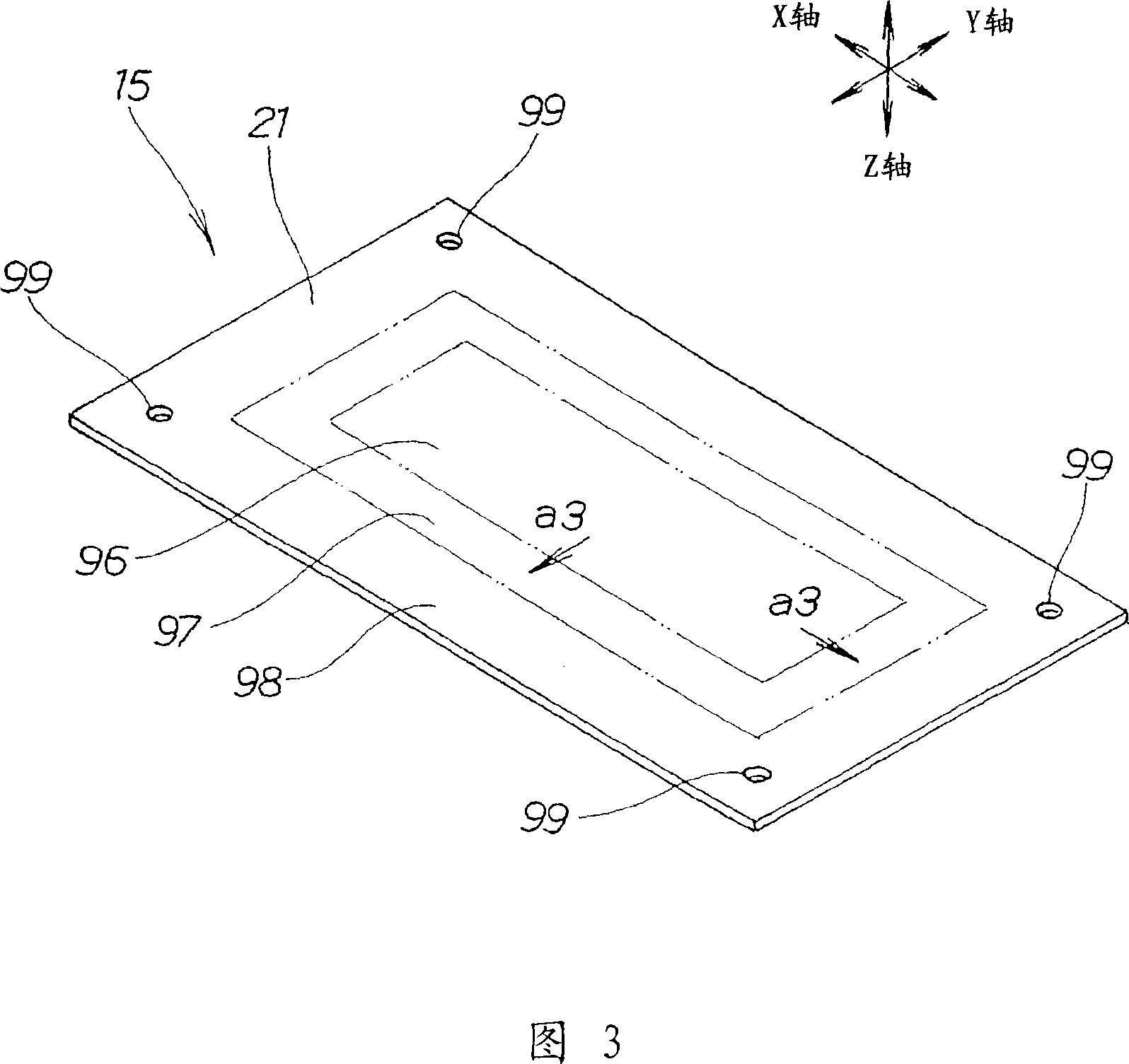
[0031] The blank holder 16 includes a first clamp device 22 that restricts the outer peripheral portion 21 of the blank 15 (restricted area 98 in FIG. 3 ), and a second clamp device 23 disposed inside the first clamp device 22 (directions of a...


PUM


Abstract

A draw forming method for drawing a blank material (15). In this method, a restraint region (98) that is an outer peripheral section (21) of the blank material is held by a first holder means (22), and then a tension region (97) inside the outer peripheral section is displaced upward by a second holder means (23) relative to the restraint region. The displacement applies tensile force to a drawing region (96) that is the central section of the blank material.

Description

technical field [0001] The present invention relates to a drawing forming method and an apparatus thereof for suppressing deflection that occurs at the center of a blank when the blank is plastically processed by a press and a die. Background technique [0002] When the billet is plastically processed by a mold installed on a press, the surrounding of the billet is pressed with a blank holder to restrict its movement, and drawing forming is performed by forming a billet, for example, in (JP) Utility Publication No. 1-153820 has a proposal in . The drawing forming will be described with reference to FIGS. 13A to 13C . [0003] In forming using the conventional drawing die 301, first, as shown in FIG. 13A , the upper mold clamp 303 of the upper mold 302 and the upper mold clamp 305 of the lower mold 304 compress the periphery of the blank B. , press the central part of the blank B with the gasket 306 and the buffer pad 307 . [0004] Next, as shown in FIG. 13B , the first-s...

Claims


Application Information

Patent Timeline
Patent Type & Authority Applications(China)
IPC IPC(8): B21D24/04B21D22/22
Inventor 堀裕一今野雄一门田隆典小野博史
Owner HONDA MOTOR CO LTD
Why Eureka
Try Eureka