Water-stopping device

A water-breaker and water-stop pad technology, which is applied to water supply devices, water supply main pipelines, water supply pipeline systems, etc., can solve the problems of limited use range, obstruction of ventilation holes, deformation of water-stop pads 15, etc. Reduce and avoid the effect of deformation

Inactive Publication Date: 2007-10-24
黄仲义
View PDF0 Cites 2 Cited by
  • Summary
  • Abstract
  • Description
  • Claims
  • Application Information

AI Technical Summary

Problems solved by technology

[0006] 1. The water-stop pad 15 is easily deformed because the locking force of the pipeline 1 is too large, and then hinders the ventilation hole 125, so that the residual water inside the pipeline 2 cannot be discharged smoothly, and the pipe may burst due to freezing in winter
[0007] 2. The body 10 is formed by interlocking the upper joint 11 and the lower joint 12. Since the external threaded part 112 and the internal threaded part 122 that can be locked with each other must be provided, the thickness of the upper joint 11 and the lower joint must be increased, so that Increased manufacturing complexity and manufacturing costs
[0008] 3. Since the body 10 is formed by interlocking the upper joint 11 and the lower joint 12, although there is a gasket 13 between the external threaded part 112 and the internal threaded part 122, it still cannot be used as a connection for a high-pressure pipeline and can only be used for The connection of low-pressure pipelines, the scope of use is limited

Method used


Image

  • Water-stopping device
  • Water-stopping device
  • Water-stopping device

Examples


Embodiment Construction

[0035] In order to enable those skilled in the art to have a deep understanding of the structure of the present invention and the functional effects that can be achieved, a specific embodiment is now listed, and the detailed description is as follows in conjunction with the accompanying drawings:

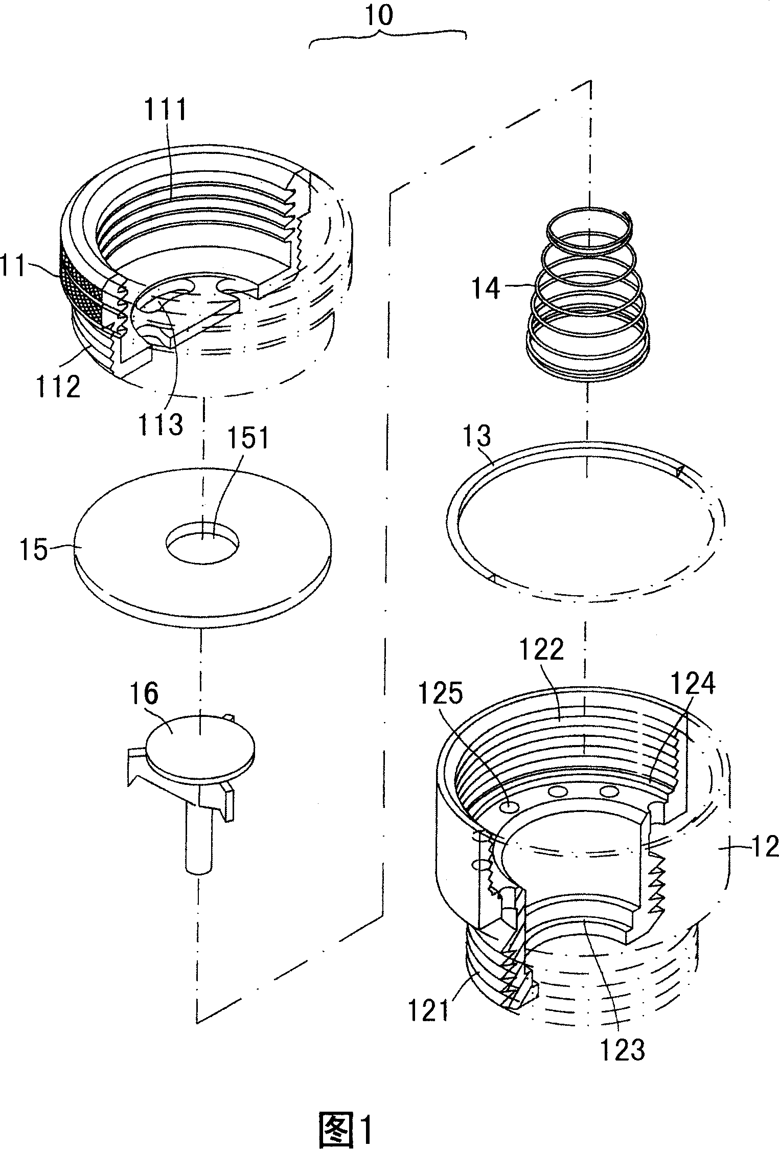
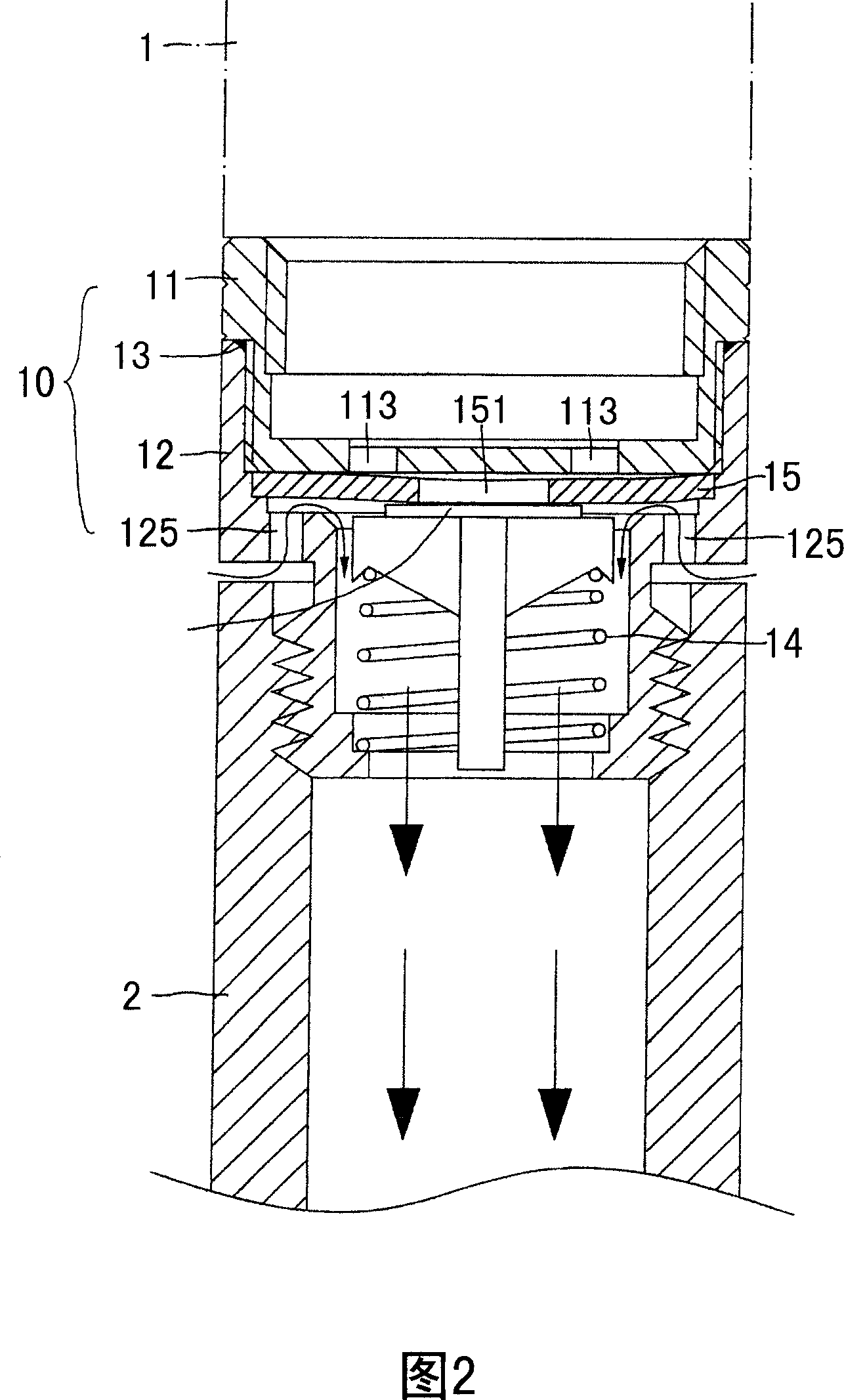
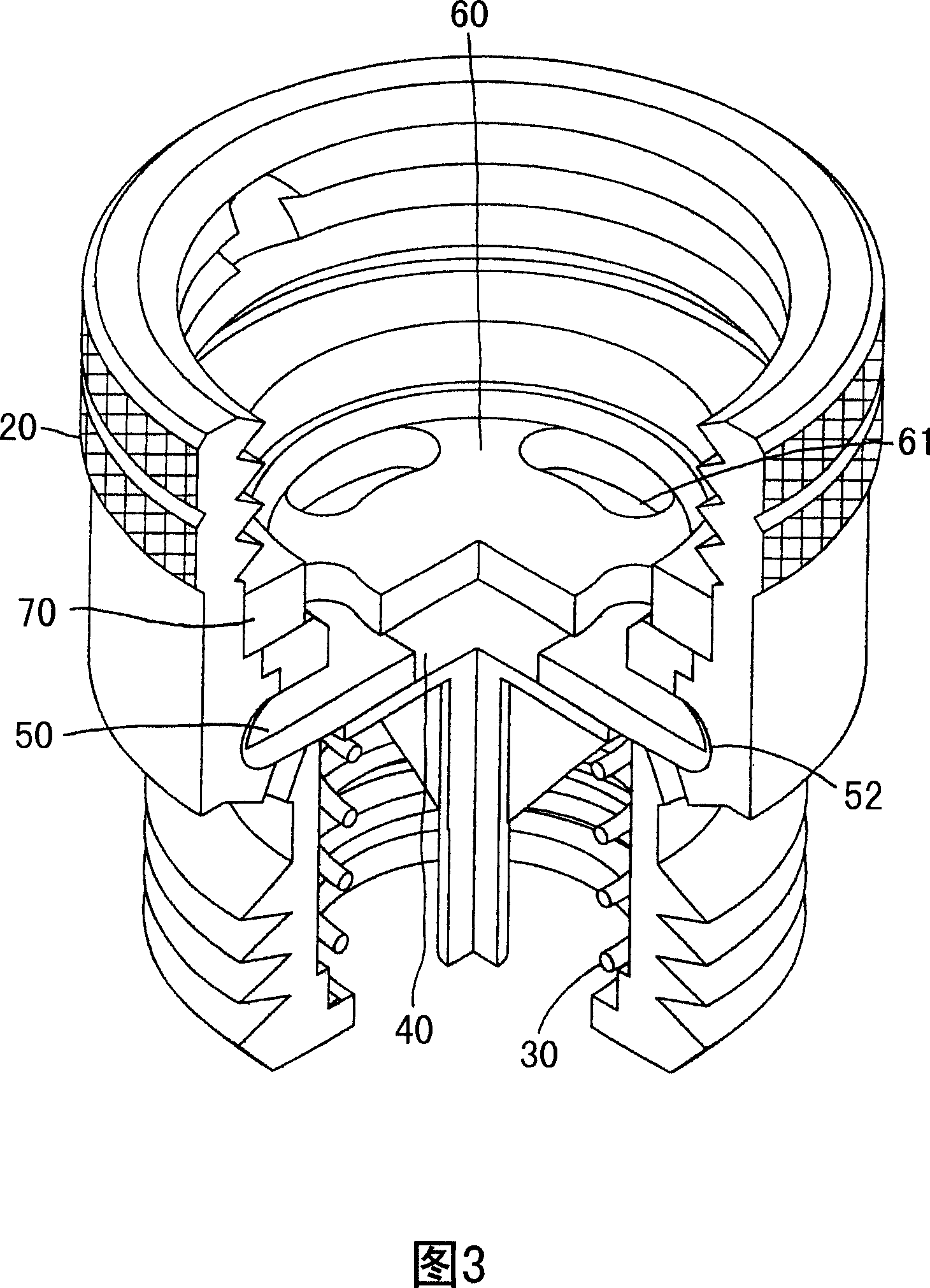
[0036] Please refer first to FIG. 3 , which shows a three-dimensional combined partial cross-sectional view of the water breaker according to the present invention. Fig. 4 shows a three-dimensional exploded view of the water breaker according to the present invention. As shown in the figure, the water breaker is mainly composed of a body 20, and an elastic element 30, a braking element 40, a water stop pad 50, a water inlet pan 60, and a washer 70 are sequentially arranged inside the body along the direction from downstream to upstream. combined; of which:

[0037] The two ends of the body 20 are provided with an internal thread portion 21 and an external thread portion 22 for lock...


PUM


Abstract

The invention provides a cut-off device, comprising a body, and an elastic element, a brake element, a water retaining pad, a water inlet disc and a washer which are arranged in the body sequentially along the direction from the downstream to the upstream; the water retaining pad is made of soft material; the water retaining pad and the water inlet disc are provided with water inlet holes; furthermore, the water inlet hole of the water retaining pad and the water inlet hole of the water inlet disc are staggered with each other; wherein, the internal wall of the body is provided with a first terrace edge, a second terrace edge, a third terrace edge and a fourth terrace edge which are respectively butted to the elastic element, the water retaining pad, the water inlet disc and the washer; the body and the position corresponding to the second terrace edge are provided with permeable holes which are communicated with the interior of the body; the circumference of the water retaining pad is provided with a labial margin which is warped upwards. As the circumference of the water retaining pad is provided with the labial margin, the elastic pressing of the water retaining pad is more flexible; meanwhile, the water retaining pad is not deformed owning to the increased locking strength of a pipeline.

Description

technical field [0001] The invention relates to a water breaker. Background technique [0002] Fig. 1 shows a three-dimensional exploded view of a traditional water breaker. The body 10 of the water breaker is mainly composed of an upper joint 11, a lower joint 12, a washer 13, an elastic element 14, a water stop pad 15, and a brake element 16; wherein: the upper joint 11 and the lower joint 12 are provided with two The inner threaded part 111 and the outer threaded part 121 of the pipelines 1 and 2 are locked, and the upper joint 11 and the lower joint 12 are provided with an outer threaded part 112 and an inner threaded part 122 that can be locked with each other at the joint, and are matched with the outer threaded part at the same time. A washer 13 is set between 112 and the internal thread portion 122. The bottom surface of the upper joint 11 is provided with a plurality of water inlet holes 113 arranged at equal intervals along the circumferential direction. The firs...

Claims


Application Information

Patent Timeline
Patent Type & Authority Applications(China)
IPC IPC(8): F17D3/01
CPCE03B7/10Y10T137/3331F16K15/141Y10T137/3294Y10T137/2557Y10T137/7895F16K15/144
Inventor 黄仲义
Owner 黄仲义
Why Eureka
Try Eureka