Plastic calendar and press polish machine
A calender and calendering technology, which is applied in the field of plastic calendering equipment, can solve the problems of low production cost, air bubbles and high production cost, and achieve the effects of high qualified rate of finished products, smooth surface and easy operation
- Summary
- Abstract
- Description
- Claims
- Application Information
AI Technical Summary
Problems solved by technology
Method used
Image


Examples
Embodiment 1
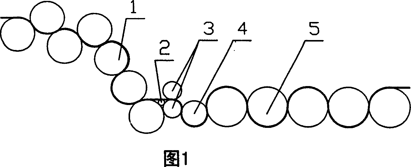
[0021] Embodiment 1: This plastic calendering calender includes a feeding mechanism, a pressure roller 1, a cooling roller 5 and its control mechanism and power mechanism. Also include stripping roll 2 and calender roll 3 between pressing roll 1 and cooling roll 5; Calender rollers 3; calender rollers 3 are two upper and lower rollers, and the spacing can be adjusted by the control mechanism to compact plastic products with a certain temperature. There is also a cold release roll 4 between the calender roll 3 and the cooling roll 5, and the cold release roll 4 is next to the calender roll 3 below.
[0022] Roller 1 is seven rollers, distributed in an "M" shape, the second roller is on the right of the first roller, the third roller is on the right of the second roller, and the fourth roller is on the third Below the first pressing roller, the fifth pressing roller is on the right of the fourth pressing roller, the sixth pressing roller is under the fifth pressing roller, the ...
Embodiment 2
[0024] Embodiment 2: The calendering calender described in embodiment 1, its press roll 1 is six rolls, is " M " type distribution, and the second press roll is on the right side of the first press roll, and the third press roll is on the right side of the first press roll. Below the second pressing roller, the fourth pressing roller is on the right of the third pressing roller, the fifth pressing roller is under the fourth pressing roller, the sixth pressing roller is under the fifth pressing roller; stripping roller 2 On the upper right side of the sixth roller.
[0025] The material enters through the first pressing roll and the second pressing roll, is output from the sixth pressing roll through extrusion and drawing, enters between the two calendering rolls through the peeling roll, and enters the cooling roll device through the cold release roll.
Embodiment 3
[0026] Embodiment 3: The calendering calender described in embodiment 1, its pressure roll 1 is five rolls, is the distribution of inverted "L" shape, and the second pressure roll is on the right side of the first pressure roll, and the third pressure roll On the right of the second pressure roller, the fourth pressure roller is above the third pressure roller, and the fifth pressure roller is above the fourth pressure roller; peeling roller 2 is on the right side of the fifth pressure roller, peeling roller 2 For two parallel existence at the same time, the gap can be adjusted through the control mechanism.
[0027] The material enters through the first pressing roll and the second pressing roll, is output from the fifth pressing roll through extrusion and drawing, enters between the two calendering rolls through the peeling roll, and enters the cooling roll device through the cold release roll.
PUM
 Abstract
Description
Claims
Application Information
 - R&D
- Intellectual Property
- Life Sciences
- Materials
- Tech Scout
- Unparalleled Data Quality
- Higher Quality Content
- 60% Fewer Hallucinations
Browse by: Latest US Patents, China's latest patents, Technical Efficacy Thesaurus, Application Domain, Technology Topic, Popular Technical Reports.
© 2025 PatSnap. All rights reserved.Legal|Privacy policy|Modern Slavery Act Transparency Statement|Sitemap|About US| Contact US: help@patsnap.com