Magnetic levitation reinforced concrete built pressing jet type wing-shape sail wind power generator

A reinforced concrete and wind turbine technology, which is applied in wind turbines, wind turbine combinations, and wind turbine control, etc., can solve the problem of difficulty in increasing the power generated by wind turbines, increasing the oncoming resistance of the sail surface, and three-dimensional space movement pollution. problem, to achieve the effect of eliminating mechanical processing, no ecological pollution, high-efficiency and high-power power generation

Inactive Publication Date: 2007-10-17
SHENZHEN WIND WATER WHEEL NEW ENERGY TECH
View PDF0 Cites 10 Cited by
  • Summary
  • Abstract
  • Description
  • Claims
  • Application Information

AI Technical Summary

Problems solved by technology

In order to improve the conversion efficiency of wind power, people have to increase the effective diameter of windmill blades. Although this has increased some wind power, it has also brought a series of contradictions that are difficult to solve; The linear speed and wind speed ratio at the tip also increase accordingly, so that modern high-tech new materials and physical structures are forced to withstand extreme blows; even if the number of blades, the horizontal axis of the impeller and the overall structure of the windmill are increased, the same Fate, not only that, because of the above physical structure characteristics, it also brings sound wave noise; ecological destruction; three-dimensional space motion pollution, etc., as well as complex process structure, high cost, short service life cycle, and the power generation of wind turbines It is also difficult to increase the power
Looking at the 3,000-year history of wind energy application by human beings, it is not difficult to find that only the ancient sail structure seems to be able to capture wind energy in a large area. Bring a series of technical problems such as large-scale structure, material, production process and manufacturing cost performance

Method used


Image

  • Magnetic levitation reinforced concrete built pressing jet type wing-shape sail wind power generator
  • Magnetic levitation reinforced concrete built pressing jet type wing-shape sail wind power generator
  • Magnetic levitation reinforced concrete built pressing jet type wing-shape sail wind power generator

Examples


Embodiment Construction

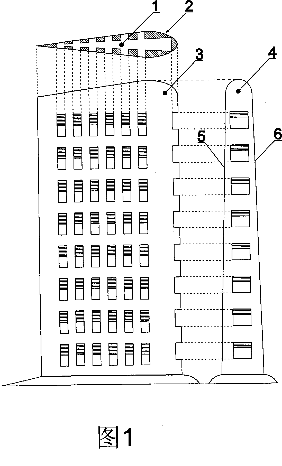
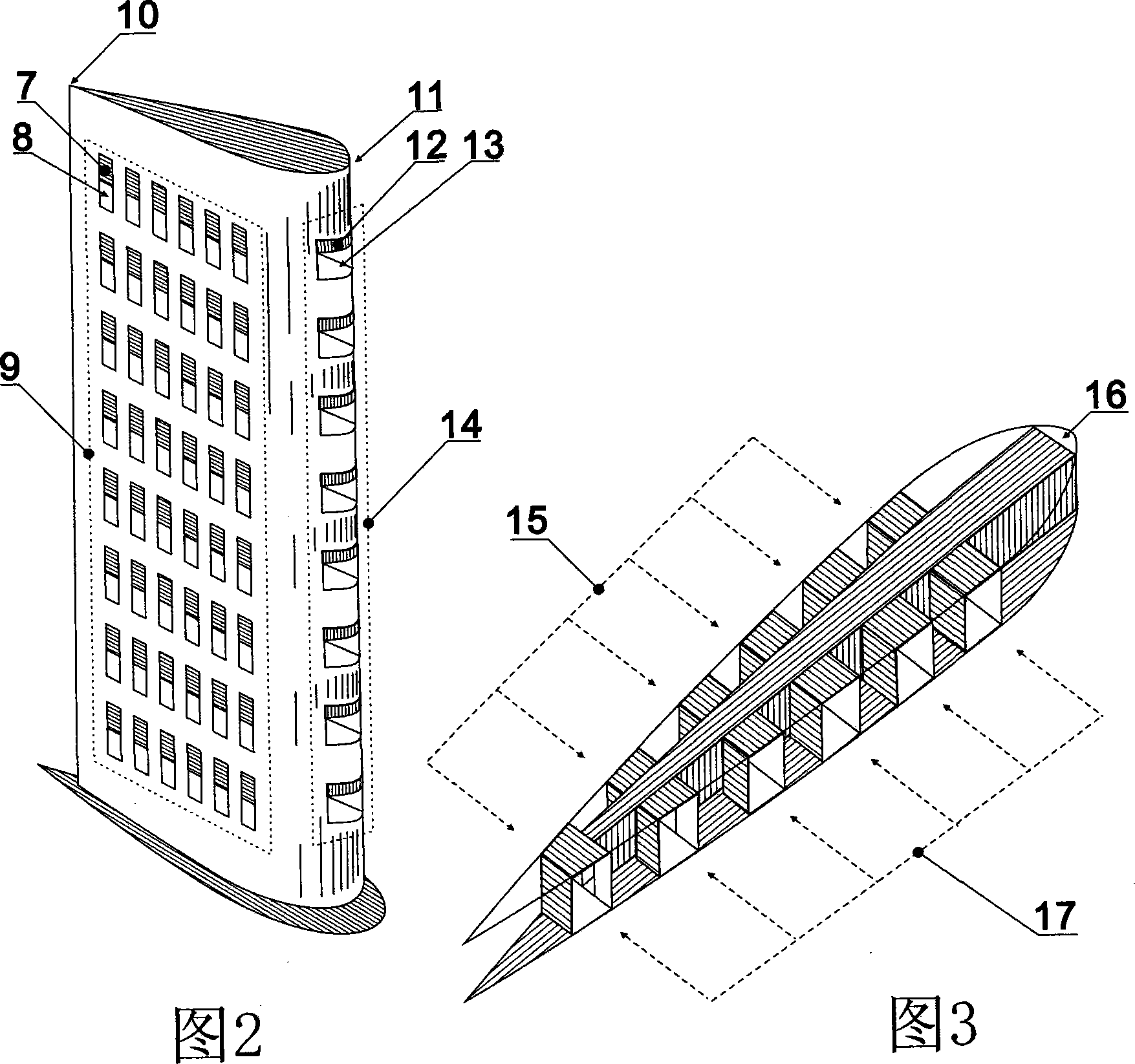
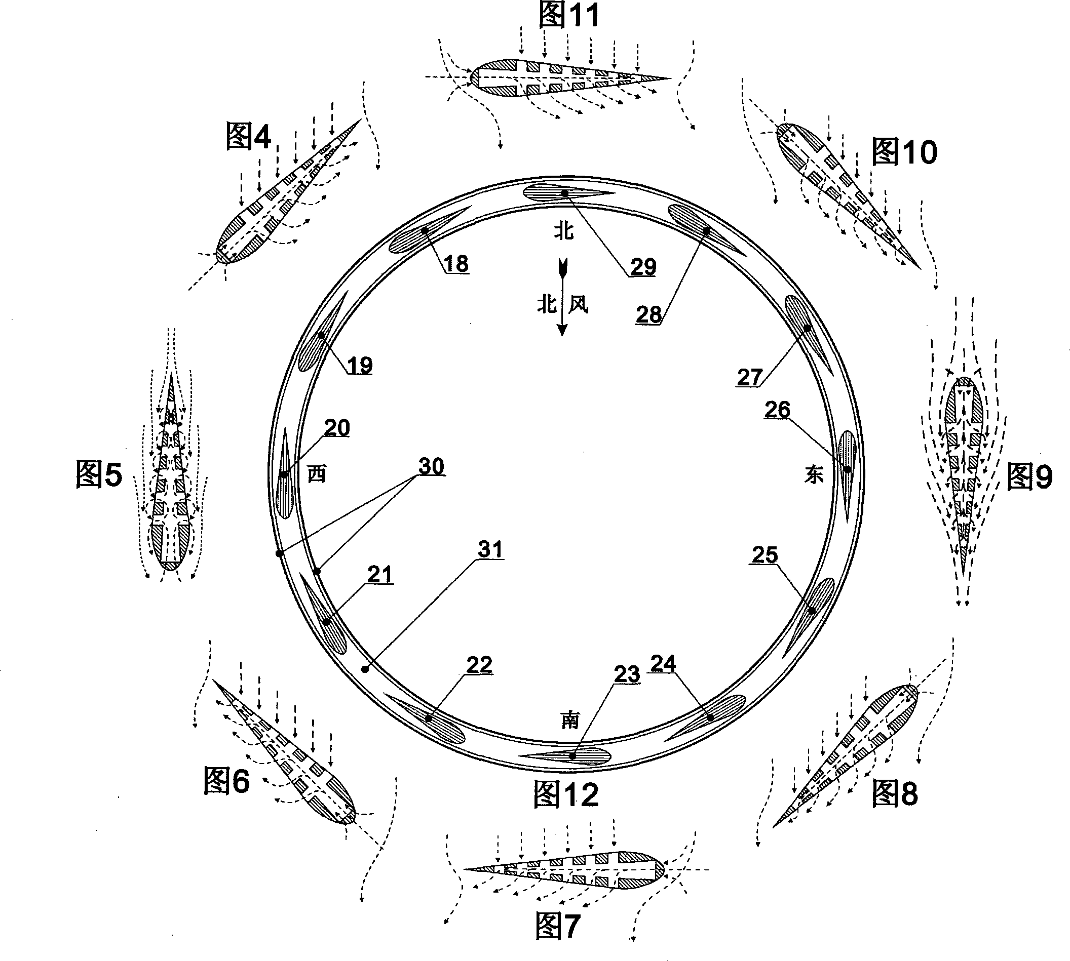
[0014] As shown in Figure 1, Fig. 2 and Fig. 3, the ramjet airfoil sail shown in Fig. 3 mainly consists of 1. jet air passage and accompanying drawings in the wingsail, and 3 six stages of ramjet units are formed, and are formed by the ramjet unit in 5. The sail surface A and 6. The two surfaces of the sail surface B are arranged in an array to form the three-dimensional structure of the stamped jet wing-shaped sail built of reinforced concrete in Fig. 2 . 18, 19, 20, 21, 22, 23, 24, 25, 26, 27, 28, 29 Each ram jet wing sail is built with reinforced concrete and evenly distributed in the magnetic levitation reinforced concrete On the annular running platform, see shown in 50,51,52,53,54,55,56,57,58,59,60,61 and 48 among Fig. 14. Reinforced concrete annular running platform 48 is suspended on a six-dimensionally oriented closed magnetic levitation track, see 44, 45, 35, 40, and the magnetic levitation can be permanent magnetic repulsion levitation or electromagnetic repulsion l...


PUM


Abstract

The present invention relates to a stamping jet type wing shape wind sail wind generator made of magnetic suspension reinforced concrete. The generator changes the inner structure of the wind sail on the base of colligating the design idea of modern aerodynamics and retaining conventional wing shape wind sail. Because the generator adopts large area and the technology principle of the stamping jet type wing shape wind sail, it increases the area of practical wind arrest for the wind generator and also greatly improves the electricity generation efficiency for single wind generator. The present invention not only adopts the structure of the stamping jet type wing shape wind sail, but also combines the modern magnetic suspension groundsill track technology, machine-electric control technology and the conventional low cost and durable reinforced concrete structure producing technics. Thereby, the whole wind generator system not only is in favor for high efficiency big power electricity generation but also has no mechanical friction, no noise, no zoology pollution and long using life. Because the main structure of the stamping jet type wing shape wind sail wind generator is entirely made of reinforced concrete, thereby it omits complex mechanical machining and reduces the producing and manufacturing cost.

Description

technical field [0001] The invention relates to a stamped jet airfoil wind-driven generator built with magnetic suspension reinforced concrete, in particular to a technical method for stamping the sail structure of the jet jet wing sail. Background technique [0002] Although wind resources are more than 10 times that of water resources! However, due to the vast space of the wind resource division, it is not as relatively concentrated as the water resource; the density of the air is only 1 / 800 of the density of water, and the air is compressible, the physical characteristics of the two are too different! This has brought many technical obstacles to the large-scale utilization of wind energy resources for human beings. At present, the mainstream horizontal axis rotor wind turbine widely used in the world has been using the traditional windmill principle, and the conversion of wind energy only relies on the limited wind receiving area of ​​the rotor blades...

Claims


Application Information

Patent Timeline
Patent Type & Authority Applications(China)
IPC IPC(8): F03D5/04F03D7/00F03D9/00F03D9/25F03D9/32
CPCY02E10/723Y02E10/725Y02E10/70Y02E10/72Y02P70/50
Inventor 李进
Owner SHENZHEN WIND WATER WHEEL NEW ENERGY TECH
Why Eureka
Try Eureka