Hydrogen storage tank and replacement method for on-off valve
A technology for storage containers and opening and closing valves, applied in container discharge methods, container filling methods, chemical instruments and methods, etc., can solve problems such as insufficient, air flowing into the main body of the container, and hydrogen storage alloys in contact with the air, etc.
- Summary
- Abstract
- Description
- Claims
- Application Information
AI Technical Summary
Problems solved by technology
Method used
Image
Examples
no. 1 Embodiment approach
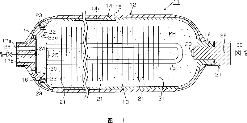
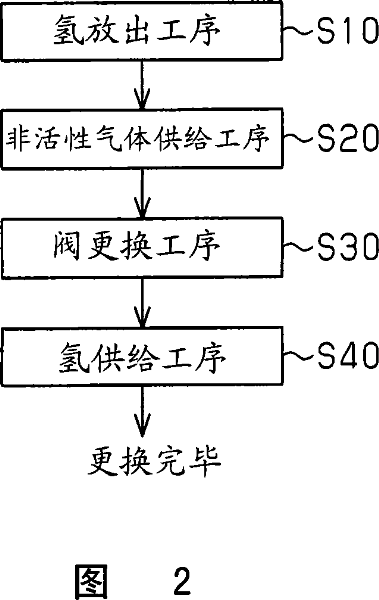
[0015] Hereinafter, a first embodiment embodying the present invention will be described with reference to FIGS. 1 and 2 .
[0016] As shown in FIG. 1 , the hydrogen storage container 11 includes: a cylindrical (cylindrical in this embodiment) container body 12 ; and a heat exchanger 13 accommodated in the container body 12 . The container body 12 is formed by forming a fiber-reinforced resin layer 15 on the outer surface of a hollow liner 14 . The fiber-reinforced resin layer 15 covers substantially the entire area of the outer surface of the liner 14 . Hydrogen gas is stored in the hydrogen storage container 11 at a pressure exceeding atmospheric pressure.
[0017] The inner liner 14 is formed of, for example, aluminum alloy, and ensures the airtightness of the hydrogen storage container 11 . Furthermore, the liner 14 is formed into a relatively elongated shape. The liner 14 is configured such that one end (base end), that is, the left end in FIG. 1 is divisible. That ...
no. 2 Embodiment approach
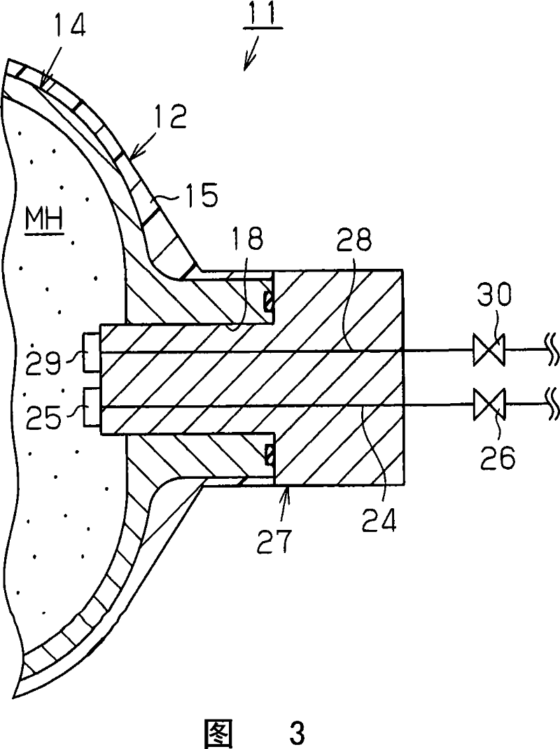
[0044] Next, a second embodiment that actualizes the present invention will be described with reference to FIG. 3 focusing on differences from the first embodiment described above.
[0045] In the present embodiment, the gas supply pipe 24 is provided on the joint 27 instead of the cover part 17 . That is, the hydrogen supply / release pipe 28 and the gas supply pipe 24 extend in parallel from the joint 27 . The on-off valves 26 and 30 provided in the two pipes 24 and 28 arranged in parallel are located in the vicinity of each other. In addition, this second embodiment is the same as the above-mentioned first embodiment in terms of the function of the hydrogen storage container 11 and the replacement procedure of the on-off valve 30 .
[0046] This embodiment has the following advantages in addition to the same advantages as the advantages (1), (3) to (6) of the first embodiment.
[0047] (7) The hydrogen supply / release pipe 28 and the gas supply pipe 24 are arranged in parall...
no. 3 Embodiment approach
[0050]Next, a third embodiment that actualizes the present invention will be described with reference to FIG. 4 focusing on differences from the first embodiment described above.
[0051] In the hydrogen storage container 40 of the present embodiment, the fiber-reinforced resin layer 15 is not formed on the outer surface of the inner liner 14 , and the container main body 12 is constituted only by the inner liner 14 . Furthermore, a gas supply pipe 24 is provided on the main body portion 14 a of the liner 14 . The gas supply pipe 24 is welded and fixed to the main body 14a while being inserted into a mounting hole formed through the outer peripheral wall of the main body 14a, thereby ensuring the airtightness of the container main body 12 . In addition, the gas supply pipe 24 is provided at a portion of the main body portion 14 a that is close to the cover portion 17 , and is spaced apart from the hydrogen supply / release pipe 28 . In addition, the third embodiment is the same...
PUM
 Abstract
Description
Claims
Application Information
 - R&D
- Intellectual Property
- Life Sciences
- Materials
- Tech Scout
- Unparalleled Data Quality
- Higher Quality Content
- 60% Fewer Hallucinations
Browse by: Latest US Patents, China's latest patents, Technical Efficacy Thesaurus, Application Domain, Technology Topic, Popular Technical Reports.
© 2025 PatSnap. All rights reserved.Legal|Privacy policy|Modern Slavery Act Transparency Statement|Sitemap|About US| Contact US: help@patsnap.com


