Light source system

A light source system and light source technology, applied in the field of light source system, can solve the problem of low light utilization rate

Inactive Publication Date: 2007-09-26
INNOCOM TECH SHENZHEN +1
View PDF0 Cites 11 Cited by
  • Summary
  • Abstract
  • Description
  • Claims
  • Application Information

AI Technical Summary

Problems solved by technology

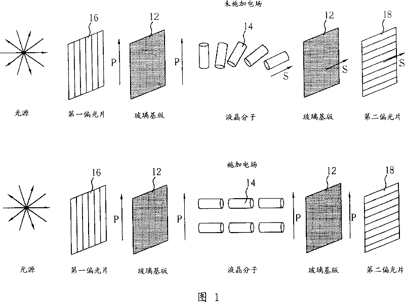
[0005] However, the function of a general polarizer is to allow linearly polarized light in a certain polarization direction to pass through the polarizer, and to absorb light perpendicular to the polarization direction, that is, to absorb 43% to 50% of the light, resulting in low light utilization

Method used


Image

  • Light source system
  • Light source system
  • Light source system

Examples


Embodiment Construction

[0051] Please refer to FIG. 2 , which is a schematic diagram of the light source system of the present invention applied to a liquid crystal display module. The liquid crystal display module 10 includes a liquid crystal display unit 12 and a light source system 14 of the present invention, wherein the light source system 14 of the present invention includes a backlight module 16 as a light source, which includes a light source generator 18, a light guide plate 24, and a reflector 20. It is used to reflect the light generated by the light source generator 18 into the light guide plate 24 , a reflection plate 22 and a plurality of optical films 26 and 28 . Since the light source generator 18 can be a lamp tube or other general light-emitting component, the light generated by the light source generator 18 is randomly polarized light, so the light emitted by the backlight module 16 is also randomly polarized light, as indicated by the arrow on the surface of the optical film 26 . ...


PUM


Abstract

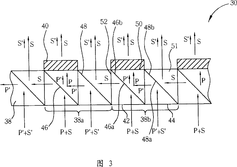
This invention provides one light source system, which comprises one light source and one module light improve deice, wherein, the improve device comprises one light bias vibration parts and one bias resonance part; the bias vibration part comprises first and second double reflection surfaces vertical to each other as reflection surfaces; through the first and second reflection surfaces and bias resonance modulation part set converts the random bias lights into light with single bias element to improve light source whole brightness.

Description

technical field [0001] The present invention provides a light source system that can be used as a backlight module of a display device, especially a light source system including a module brightness enhancement device. Background technique [0002] Because of the characteristics of thin and light appearance, low power consumption and no radiation pollution, liquid crystal display is a display device that is becoming increasingly popular, and has been widely used in personal desktop computer screens, notebook computers, personal digital assistants (PDAs). ), mobile phones and other portable information products, and gradually replace Cathode Ray Tube (CRT) monitors and traditional TVs. [0003] Generally speaking, a liquid crystal display module (LCM) is the most critical device in a liquid crystal display, which includes components such as a liquid crystal display panel and a backlight module. A liquid crystal display panel is formed by setting a liquid crystal molecule lay...

Claims


Application Information

Patent Timeline
Patent Type & Authority Applications(China)
IPC IPC(8): G02F1/13357G02F1/1335
Inventor 黎瑞雍游川倍
Owner INNOCOM TECH SHENZHEN
Why Eureka
Try Eureka