Steering damper device
A technology of shock absorber and shock absorber, which is applied in the direction of steering mechanism, transportation and packaging, bicycle accessories, etc., which can solve the problems of difficulty in maintaining angle-dependent characteristics of handle steering angle, inability to realize miniaturized layout, difficulty in attenuation force, etc.
- Summary
- Abstract
- Description
- Claims
- Application Information
AI Technical Summary
Problems solved by technology
Method used
Image

Examples
Embodiment 1
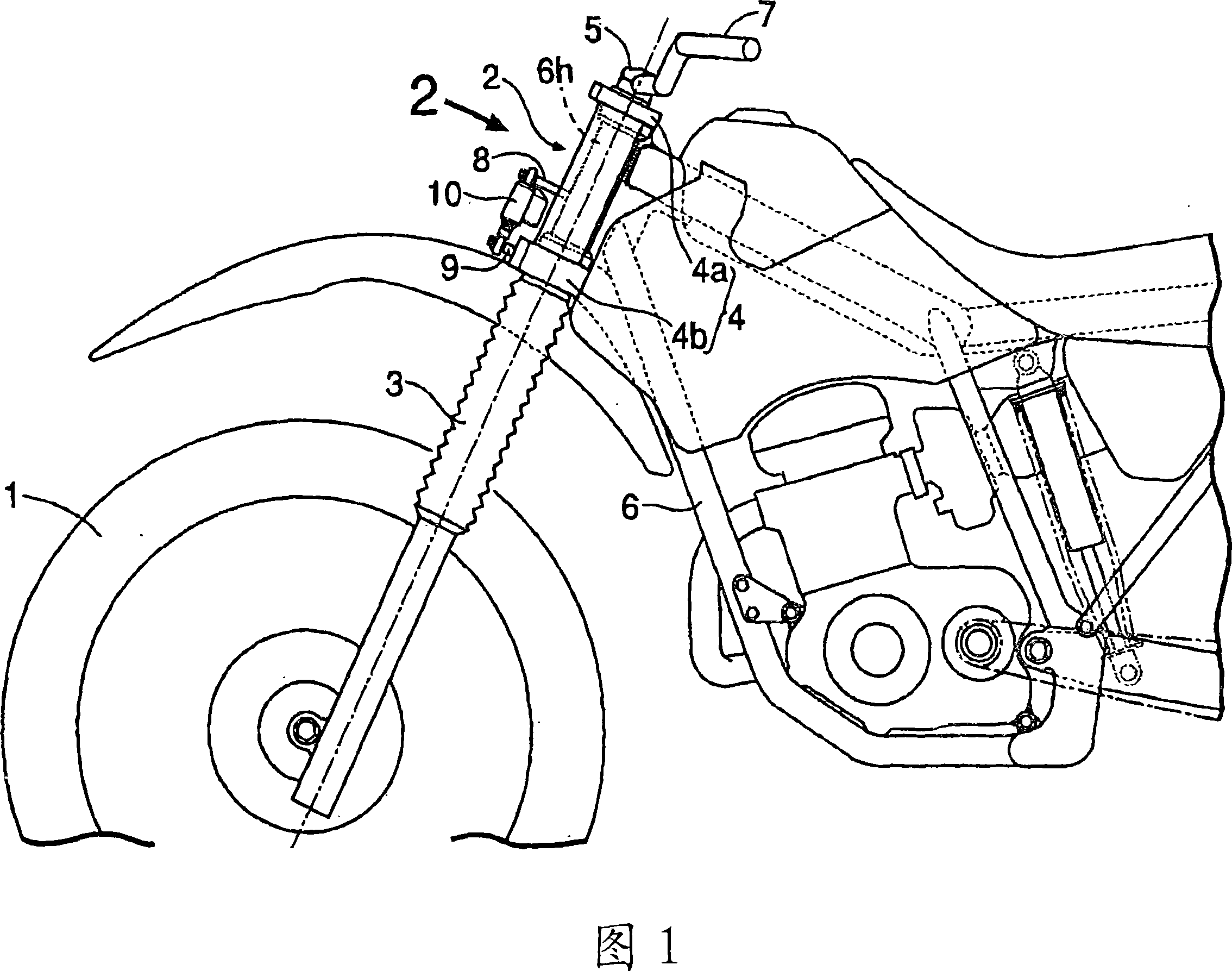
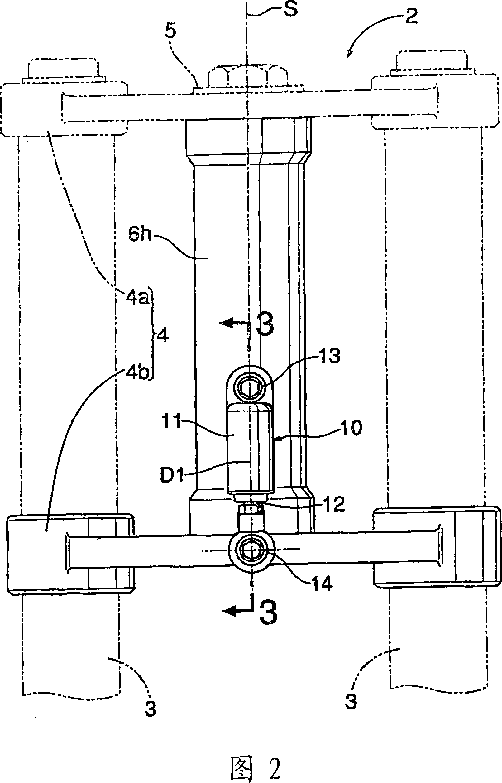
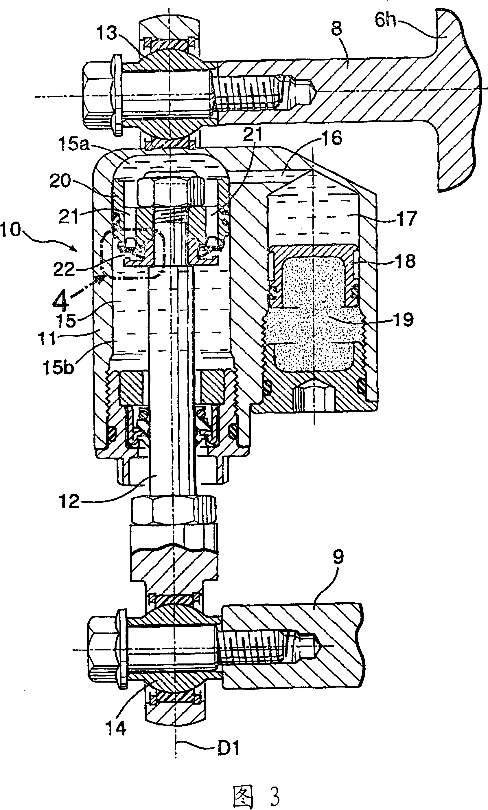
[0057] Among the figures, Fig. 1 to Fig. 8 show the first embodiment according to the steering damper device of the present invention, Fig. 1 is a side view showing the essential parts of a motorized two-wheeled vehicle equipped with the steering damper device, Fig. 2 is The front view of the front fork seen from the direction of arrow 2 in Fig. 1, Fig. 3 is a cross-sectional view of the cylinder shock absorber part along the line 3-3 in Fig. 2, Fig. 4 and Fig. 5 are for the cylinder Figure 6 is an enlarged view illustrating the function of the type shock absorber, Fig. 6 is a front view similar to Fig. 2 showing the state when the handle is switched to the left, and Fig. 7 is a cross-sectional view along line 7-7 in Fig. 6, Fig. 8 is a characteristic graph of the steering damper device.
[0058] As shown in FIGS. 1 and 2 , a front fork 2 supporting a front wheel 1 of a motorcycle has left and right fork pipes 3 , 3 and a fork bridge 4 connecting the upper ends thereof. The f...
Embodiment 2
[0073] 9 to 13 show a second embodiment of the steering damper device according to the present invention. FIG. 9 is a side view showing the main parts of a motorcycle equipped with the steering damper device. FIG. 10 is a view from FIG. 9 Figure 11 is a cross-sectional view of the barrel shock absorber along the line 11-11 in Figure 10, Figure 12 is a diagram showing the state when the handle is switched to the left 10 is the same plan view, and Fig. 13 is a sectional view along line 13-13 in Fig. 12 .
[0074] In addition, in the second embodiment, parts corresponding to those in the first embodiment are assigned the same reference numerals, and thus redundant explanations are omitted.
[0075] As shown in FIGS. 9 and 10 , in the case of the second embodiment, a brace protruding upward is provided at a position in front of the steering rod 5 on the upper central portion of the top bridge 4 a forming the upper part of the fork bridge 4 . Article 28. Further, an extension por...
Embodiment 3
[0082] 14 and FIG. 15 show a third embodiment of the steering damper device according to the present invention. FIG. 14 is a plan view showing the front fork of a motorcycle equipped with the steering damper device. FIG. The side view seen in the direction of arrow 15.
[0083] In addition, in this third embodiment, parts corresponding to those in the second embodiment are given the same reference numerals, and thus redundant explanations are omitted.
[0084] As shown in FIG. 14 and FIG. 15, in the case of the third embodiment, on the upper surface of the extension portion 6j extending rearward from the upper end portion of the head pipe 6h, a substantially triangular link 38 is freely rotatable via a horizontal shaft 39. to be supported. Further, a cylindrical damper 40 is arranged between the link 38 and the down tube 6d between the left and right main frames 6m, 6m constituting the vehicle body frame 6 together with the head pipe 6h. The cylindrical damper 40 is composed...
PUM
 Abstract
Description
Claims
Application Information
 - R&D
- Intellectual Property
- Life Sciences
- Materials
- Tech Scout
- Unparalleled Data Quality
- Higher Quality Content
- 60% Fewer Hallucinations
Browse by: Latest US Patents, China's latest patents, Technical Efficacy Thesaurus, Application Domain, Technology Topic, Popular Technical Reports.
© 2025 PatSnap. All rights reserved.Legal|Privacy policy|Modern Slavery Act Transparency Statement|Sitemap|About US| Contact US: help@patsnap.com