
Chip low temperature co-fired ceramic co-mode filter

A low-temperature co-fired ceramic and common-mode filter technology, applied in waveguide-type devices, inductors, fixed inductors, etc., can solve problems such as poor impedance characteristics, failure to filter noise, and inability to effectively reduce differential mode impedance. Achieve the effect of reducing line spacing requirements, low processing difficulty, and reducing electromagnetic leakage

Active Publication Date: 2007-09-19
HUAZHONG UNIV OF SCI & TECH +1
View PDF0 Cites 9 Cited by
  • Summary
  • Abstract
  • Description
  • Claims
  • Application Information

AI Technical Summary

Problems solved by technology

However, due to the limitation of its own structure and the influence of the processing accuracy of the process line, its impedance characteristics are worse than the former two, and the differential mode impedance cannot be effectively reduced to the requirements of special specifications.
This makes the signal receiving end unable to effectively receive the signal when the signal passes through the common mode filter.
Does not meet the requirements of filtering out noise and passing the signal

Method used


Image

  • Chip low temperature co-fired ceramic co-mode filter
  • Chip low temperature co-fired ceramic co-mode filter
  • Chip low temperature co-fired ceramic co-mode filter

Examples


Embodiment Construction

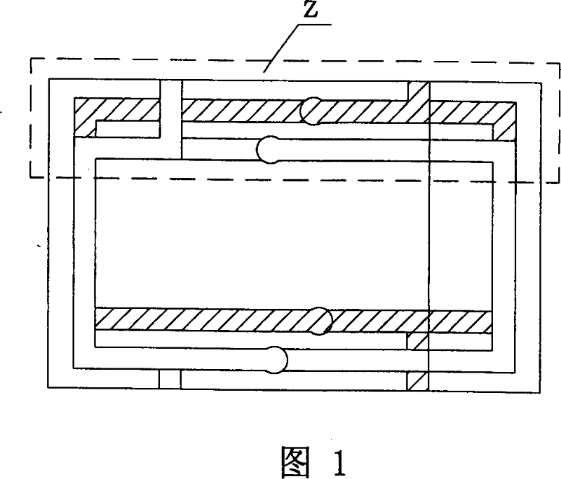
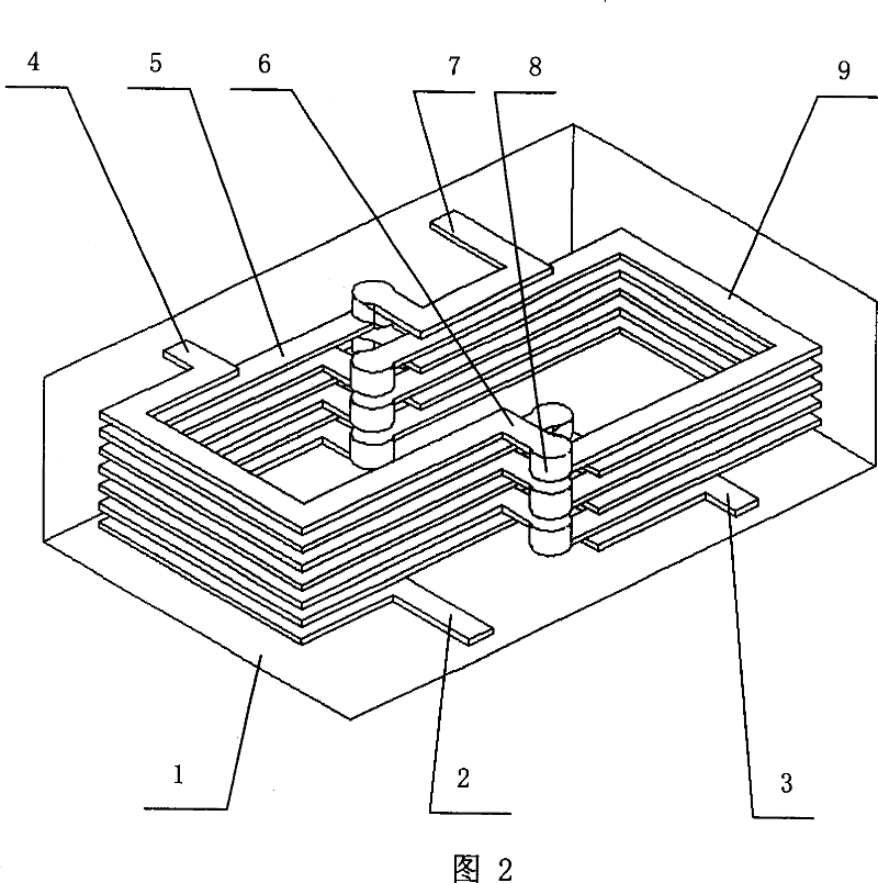
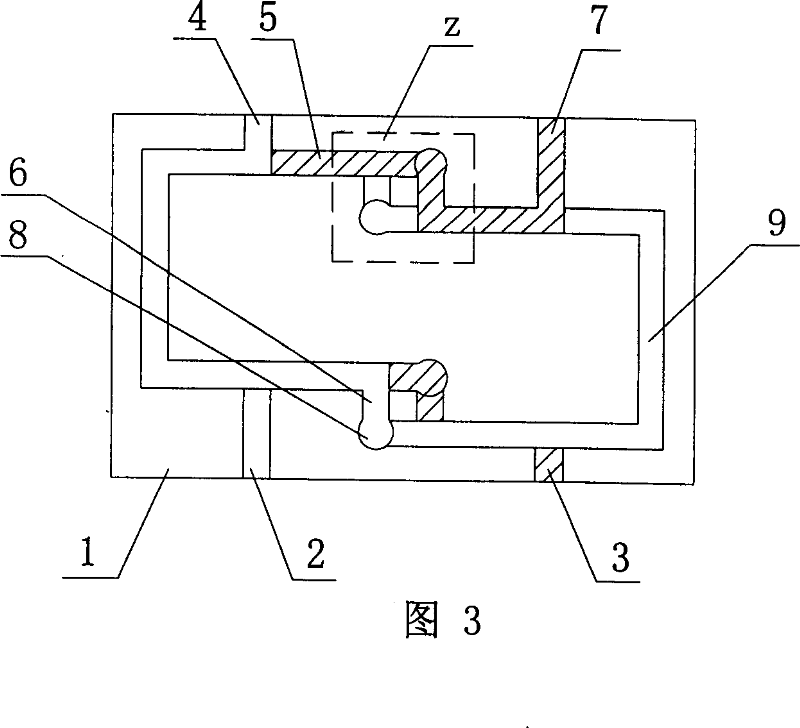
[0029] As shown in Figure 2 and Figure 3, the chip type low temperature co-fired ceramic common mode filter (n is 7 in this example, the printing of each layer is shown in Figure 4-1, Figure 4-2, Figure 4-3, Figure 4 -4, shown in Fig. 4-5, Fig. 4-6), it is made of low-temperature co-fired ceramic body 1 by stacking tape-cast green tapes, and there are 7 layers of left and right layers printed on the low-temperature co-fired ceramic body. Coil and right coil, the 7th layer and the 1st layer are pin layers respectively; one end of the left coil 4 on the 7th layer is connected to one end of the right coil 9 on the 6th layer by a joint 8 (Note: in Figure 2, outside the figure The joint is one end, the joint in the picture is the other end, and the pin is the outer end), the other end of the right coil 9 on the 6th layer is connected with the other end of the left coil on the 5th layer by a joint; the right coil on the 7th layer The other end of 7 is connected with the other end of...


PUM


Abstract

The invention relates to a low-temperature co-fired ceramic common mode filter for eliminating signal interference on an electronic apparatus. A sheet type low-temperature co-fired ceramic common mode filter produces a low-temperature co-fired ceramic by laminating tape-casted unripe ceramic tapes, n layers of left coils and right coils are printed in the low-temperature co-fired ceramic, where n>=5, an n-th layer and a first layer are pin layers respectively; the filter is characterised in that: a joint heat of a left coil's end of a lower layer and a right coil's end of an upper layer is stagger with a joint head of a left coil's end of the upper layer and a right coil's end of a more upper layer, and a joint heat of the other end of a right coil of the lower layer and the other end of the left coil of the upper layer is stagger with a joint heat of the other end of a right coil of the upper layer and the other end of the left coil of the more upper layer. The invention has characteristic of more ideal high-frequency performance, low differential mode impedance and low manufacturing cost.

Description

technical field [0001] The invention relates to a low-temperature co-fired ceramic common-mode filter for eliminating signal interference of electronic equipment. technical background [0002] There are currently two main types of chip common mode filters, which are multi-layer chip and wire-wound. The wire-wound filter has better electrical performance, but the cost is high, and it is not suitable for large-scale use in electronic products. . One of the multi-layer chips is a double-layer coupled ferrite structure. Due to the characteristics of the ferrite material itself, the loss in the high-frequency band is too large. When the device is used in the high-frequency band, the useful differential The mode signal causes great attenuation, which affects the circuit performance, so it is only suitable for lower frequency bands; on the other hand, the dielectric constant of the ferrite material is relatively high. In order to meet the characteristic impedance requirements of t...

Claims


Application Information

Patent Timeline
Patent Type & Authority Applications(China)
IPC IPC(8): H01F17/00H01F27/28H01P1/215
Inventor 徐勤芬吴国安毕晓君叶长河伍隽汤清华
Owner HUAZHONG UNIV OF SCI & TECH
Learn More