Refrigerator
A technology for refrigerators and radiators, which is applied in the field of refrigerators operating in a supercritical state on the high-pressure side. It can solve the problems of cooling obstacles, the decline of refrigeration capacity at the evaporator, and the inability to drop the temperature of refrigerants, so as to be beneficial to environmental problems and prevent The effect of temperature rise
- Summary
- Abstract
- Description
- Claims
- Application Information
AI Technical Summary
Problems solved by technology
Method used
Image
Examples
Embodiment 1
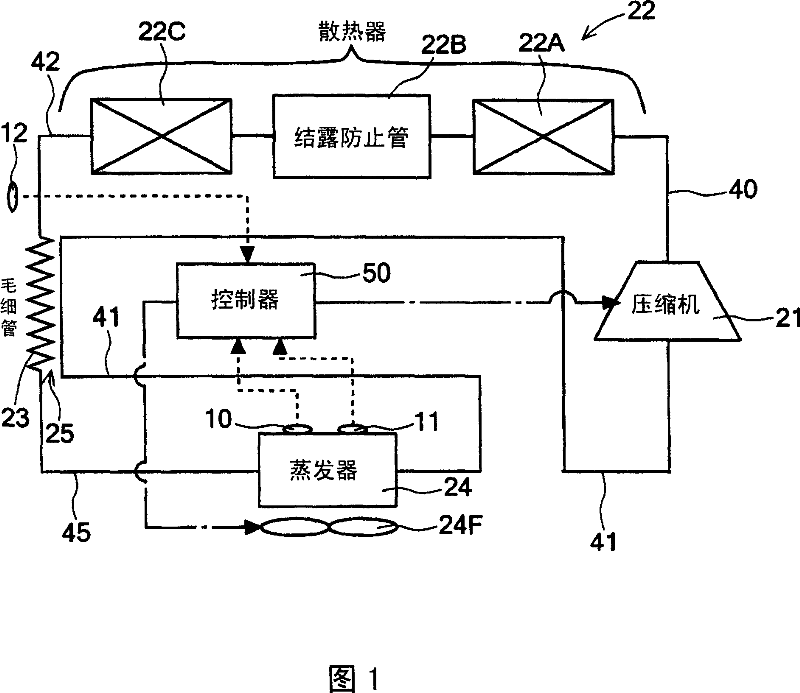
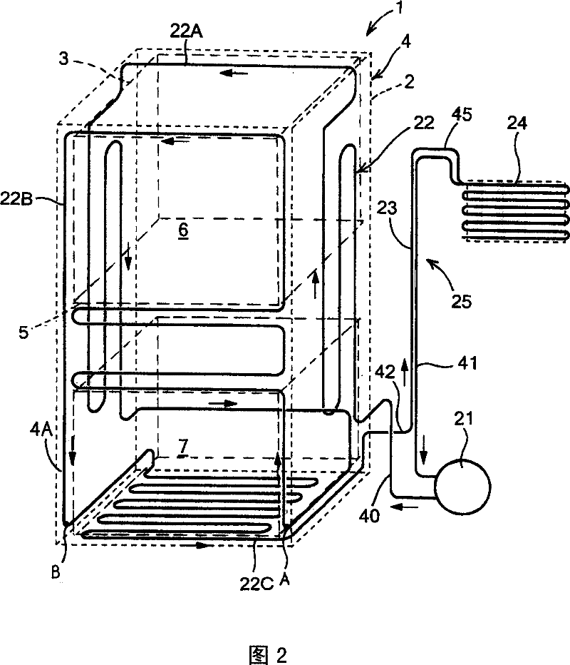
[0032] FIG. 1 shows a refrigerant circuit diagram of an embodiment of a refrigerator according to the present invention, and FIG. 2 shows a schematic diagram of a dew condensation prevention pipe added to an opening edge of an insulating box of the refrigerator. The body of the refrigerator 1 of the embodiment is composed of the following parts: an outer box 2 made of steel plate with an opening at the front; an inner box 3 made of thin-walled hard synthetic resin (such as ABS resin); An insulating box 4 made of a heat insulating material such as foamed polyurethane; and an insulating door (not shown) that closes the front opening of the insulating box 4 freely.
[0033] The interior of the heat-insulating box 4 is divided up and down by the partition wall 5. For example, the top of the partition wall 5 is used as a refrigerating room 6 cooled to a refrigeration temperature (for example, about +5° C.), and the bottom of the partition wall 5 is used as a room for freezing to a f...
Embodiment 2
[0062] In addition, in Embodiment 1, the capillary 23 was used as the decompression device, but as shown in FIG. . In the case of this embodiment, the refrigerant piping 42 before the expansion valve 26 (on the upstream side of the expansion valve 26 ) and the suction side piping 41 flowing out of the evaporator 24 are arranged so as to perform heat exchange, thereby constituting an internal heat exchanger. 27. The refrigerant circuit of the refrigerator of this embodiment shown in FIG. 4 is the same as the above-mentioned embodiment 1 in many points, so the structures that are the same as the refrigerator 1 of embodiment 1 or have the same function or effect are omitted. Detailed description.
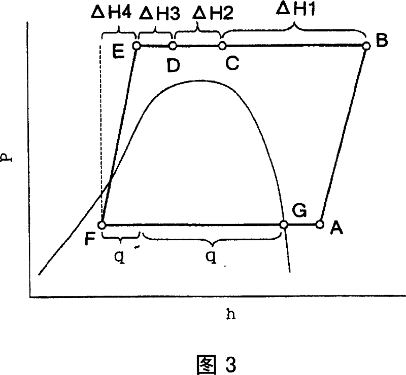
[0063] Next, the operation of the refrigerator 1 of this embodiment will be described using the Mollier diagram of FIG. 5 . The basic control operation by the controller 50 is the same as that of the first embodiment, so detailed description is omitted.
[0064] Then, when the temp...
Embodiment 3
[0074] In addition, by moving the dew condensation prevention pipe 22B from the downstream region of the conventional radiator to the upstream region as described in each of the above-mentioned embodiments, there is no particular obstacle during normal operation, but it may cause problems when descending or at a high temperature. At the time of load, the temperature of the refrigerant flowing through the dew condensation prevention pipe 22B may become too high. That is, if the temperature of the refrigerant on the high-pressure side of the refrigerant circuit rises abnormally at the time of falling or high load, the refrigerant cannot be sufficiently radiated in the heat radiation of the refrigerant pipe 22A in the refrigerant upstream region of the radiator 22 . Since the temperature becomes low, high-temperature refrigerant may flow in the dew condensation prevention pipe 22B. Since the dew condensation prevention pipe 22B is located at the opening edge 4A of the heat insula...
PUM
 Abstract
Description
Claims
Application Information
 - Generate Ideas
- Intellectual Property
- Life Sciences
- Materials
- Tech Scout
- Unparalleled Data Quality
- Higher Quality Content
- 60% Fewer Hallucinations
Browse by: Latest US Patents, China's latest patents, Technical Efficacy Thesaurus, Application Domain, Technology Topic, Popular Technical Reports.
© 2025 PatSnap. All rights reserved.Legal|Privacy policy|Modern Slavery Act Transparency Statement|Sitemap|About US| Contact US: help@patsnap.com


