Method and device of eliminating dust

A technology for a dust removal device and a dust removal chamber, which is applied in cleaning methods and utensils, chemical instruments and methods, cleaning methods using gas flow, etc., to achieve the effect of preventing re-attachment

Inactive Publication Date: 2007-09-19
SEIKO EPSON CORP
View PDF1 Cites 7 Cited by
  • Summary
  • Abstract
  • Description
  • Claims
  • Application Information

AI Technical Summary

Problems solved by technology

[0004] However, there is a problem that if the compressed air is simply blown on the parts, the dust removed from the parts may fly around in the dust removal device and adhere to the parts again

Method used


Image

  • Method and device of eliminating dust
  • Method and device of eliminating dust
  • Method and device of eliminating dust

Examples


Embodiment approach

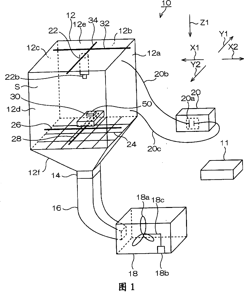
[0037] FIG. 1 is a schematic perspective view showing a dust removal device 10 according to an embodiment of the present invention.

[0038] The dust removal device 10 is an example of a dust removal device.

[0039] As shown in FIG. 1 , the dust removal device 10 has a dust removal chamber 12 . The dust removal room 12 is an example of a dust removal room.

[0040] The dust removal device 10 has a control device 11 for controlling each part. Although the control device 11 is connected to each part, illustration of the connection state is omitted. The control device 11 is an example of a control device.

[0041] The dust removal chamber 12 has a holding stand 30 for holding the parts 50 . The holding table 30 is an example of a holding table. Part 50 is an example of a processing target. Part 50 is, for example, a part of a projector which is a precision device.

[0042] The dust removal chamber 12 has side walls 12a, 12b, 12c and 12d. The side walls 12a and the like a...


PUM


Abstract

Provided is a dust collector and a dedusting method which reliably prevents the removed dust from the parts again attached on the parts. The dust collector 18 includes: a dust chamber 12 for keeping the maintaining station 30 of the processed object 50; an air jet device 22 for blowing the air on the processed object 50; and a negative pressure generating device 18 for attracting the dust from the dust chamber 12, which is characterized in that, the negative pressure generating device 18 is composed in a continuous action for the given time after completing the dedust.

Description

technical field [0001] The present invention relates to a dust removal device and a dust removal method used in the manufacturing process of precision equipment. Background technique [0002] Conventionally, in the process of manufacturing components of precision equipment, a dust removal device for removing foreign matter such as dust adhering to each component by blowing compressed air to the components is used (for example, Patent Document 1). [0003] Patent Document 1: JP-A-2005-199169 [0004] However, there is a problem that if the compressed air is simply blown to the parts, the dust removed from the parts may fly around in the dust removal device and adhere to the parts again. Contents of the invention [0005] Therefore, an object of the present invention is to provide a dust removal device and a dust removal method capable of reliably preventing the dust removed from parts from adhering to the parts again. [0006] Aforesaid object, according to the first inve...

Claims


Application Information

Patent Timeline
Patent Type & Authority Applications(China)
IPC IPC(8): B08B5/00B08B6/00
Inventor 伊藤文人
Owner SEIKO EPSON CORP
Why Eureka
Try Eureka