Electric vacuum cleaner

A vacuum cleaner, electric technology, applied in vacuum cleaners, suction filters, chemical instruments and methods, etc., can solve problems such as complex structure

Inactive Publication Date: 2007-10-03
TOSHIBA LIFESTYLE PROD & SERVICES CORP
View PDF1 Cites 5 Cited by
  • Summary
  • Abstract
  • Description
  • Claims
  • Application Information

AI Technical Summary

Problems solved by technology

[0008] However, in this type of electric vacuum cleaner, it is necessary to provide an interlocking mechanism that interlocks the switching operation of the switch member with the pulling or winding operation of the power cord, and there is a problem that the structure becomes complicated.

Method used


Image

  • Electric vacuum cleaner
  • Electric vacuum cleaner
  • Electric vacuum cleaner

Examples


Embodiment

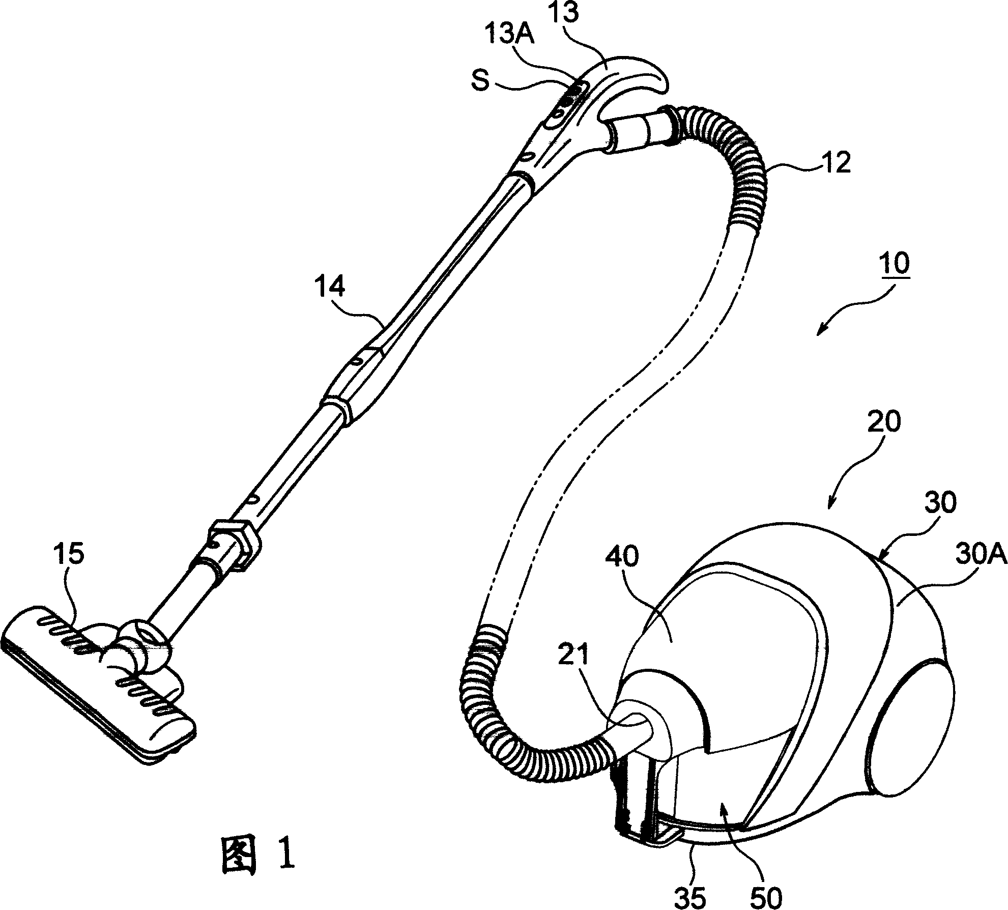
[0023] The electric vacuum cleaner 10 shown in FIG. 1 includes a vacuum cleaner main body 20, and on the hose connection port 21 provided on the front portion of the vacuum cleaner main body 20, one end of the dust collection hose 12 is detachably connected, and on the other end A manual operation unit 13 is provided. An extension pipe 14 is detachably connected to the manual operation part 13 , and a suction port body 15 is detachably connected to the distal end portion of the extension pipe 14 . Furthermore, an operation unit 13A is provided on the manual operation unit 13 , and a plurality of operation switches S are provided on the operation unit 13A.

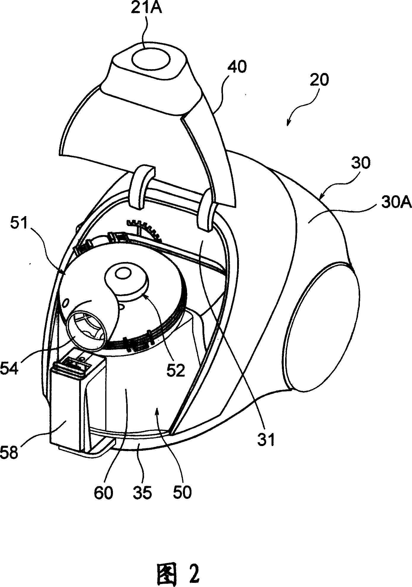
[0024] The vacuum cleaner main body 20, as shown in FIG. 2 , includes: a main body shell 30; a dust collecting container 50, which is mounted on the main body shell 30 in a detachable manner; 30, and can switch in the up and down direction.

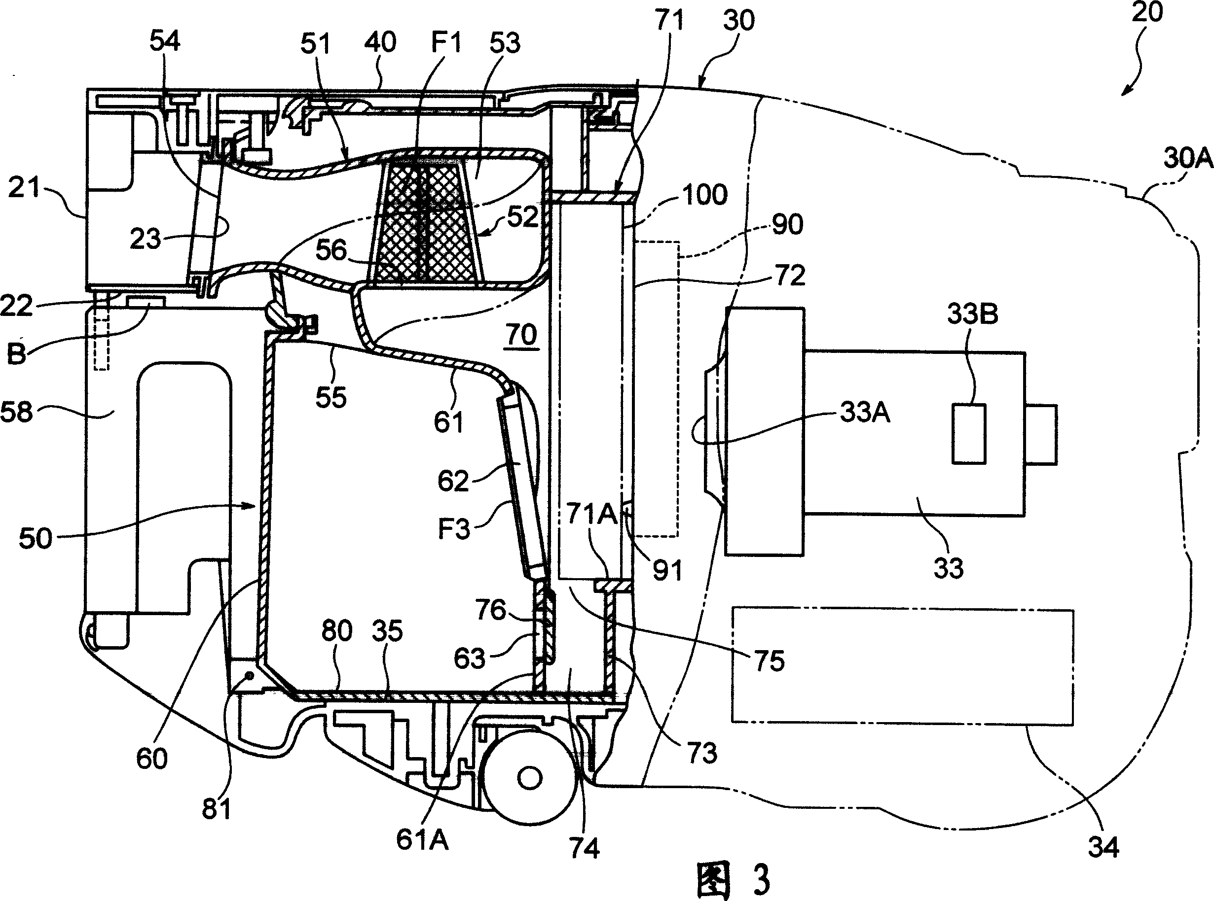
[0025] Furthermore, an electric blower 33 (see FIG. 3 ) is built in the rear por...


PUM


Abstract

An electric vacuum cleaner (10) includes a first dust separation device (F3) configured to separate sucked dust, a first dust collection section (60) for collecting the separated dust, a second dust separation device (100) configured to separate the dust, a dust removing device (90) configured to remove the dust adhering to the second dust separation device (100), a second dust collection section (74) for accumulating the removed dust, a partition wall (61) for zoning the first dust collection section (60) and the second dust collection section (74) and an introduction opening (75) for introducing the removed dust into the second dust collection section (60); the partition wall (61) includes a communication opening (63) for communicating the first dust collection section (60) to the second dust collection section (74) and an opening and closing member (76) for closing either of the introduction opening (75) or the communication opening (63) and switching the closing to the other by rotating, and the opening and closing member (76) closes the introduction opening (75) with a negative pressure by an electric fan (33) and closes the communication opening (63) by its own weight when the electric fan (33) is not driven.

Description

technical field [0001] The present invention relates to an electric vacuum cleaner including first and second dust separation devices for separating suctioned dust. Background technique [0002] In the prior art, there is known an electric vacuum cleaner comprising a first dust separation device and a second dust separation device, wherein the first dust separation device separates the dust, and the second dust separation device passes through the first dust separation device. Dust is separated by a dust separation device (see Patent Document 1). [0003] The electric vacuum cleaner includes: a first dust separation device that separates the dust attracted by the negative pressure of the electric blower; a first dust collection unit that collects the dust separated by the first dust separation device; A dust separation device, which separates the dust passing through the first dust separation device; a dust removal device, which removes the dust attached to the second dust ...

Claims


Application Information

Patent Timeline
IPC IPC(8): A47L5/12A47L9/10
CPCA47L9/20A47L9/102Y10S55/03
Inventor 大津育弘田中正俊大塚裕司町田幸雄渡邉满
Owner TOSHIBA LIFESTYLE PROD & SERVICES CORP
Why Eureka
Try Eureka