
Rotary electrical component

An electrical component, rotary type technology, applied in the direction of electrical components, circuits, electrical switches, etc., can solve the problems of pulling out the operation shaft and weakening the strength of the operation shaft, and achieve the effect of preventing it from being pulled out and improving the pulling strength.

Active Publication Date: 2007-09-05
ALPS ALPINE CO LTD
View PDF1 Cites 4 Cited by
  • Summary
  • Abstract
  • Description
  • Claims
  • Application Information

AI Technical Summary

Problems solved by technology

[0012] However, in the above-mentioned conventional rotary electric component, since the installation of the operation shaft is implemented by fastening and fixing the pair of elastic mounting legs on the locking part of the driving body, the operation shaft is in the pulling direction. When the strength of the operation shaft is weakened, when the operation shaft is pulled out by a large force, there is a problem that the operation shaft may be pulled out.

Method used


Image

  • Rotary electrical component
  • Rotary electrical component
  • Rotary electrical component

Examples


Embodiment Construction

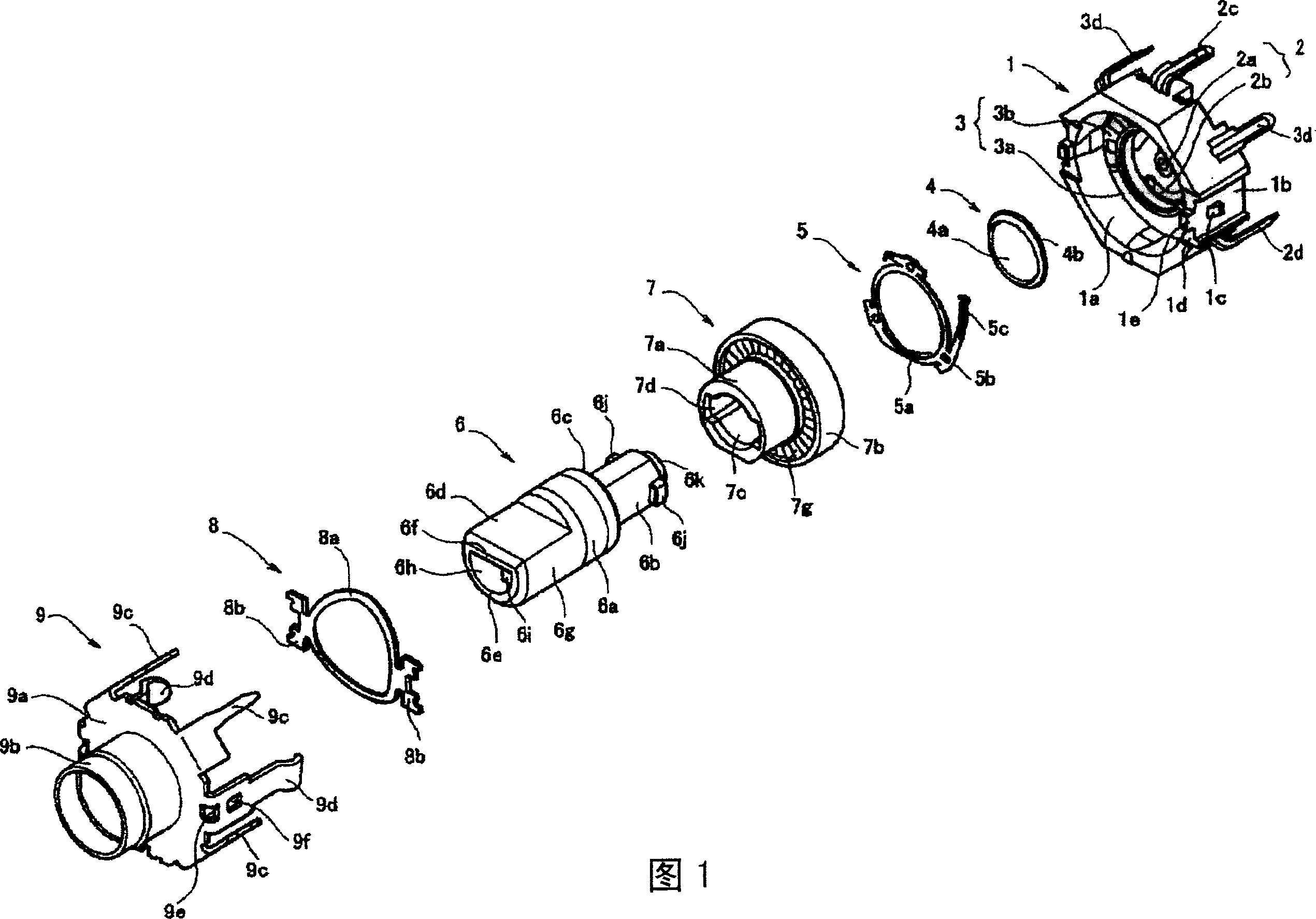
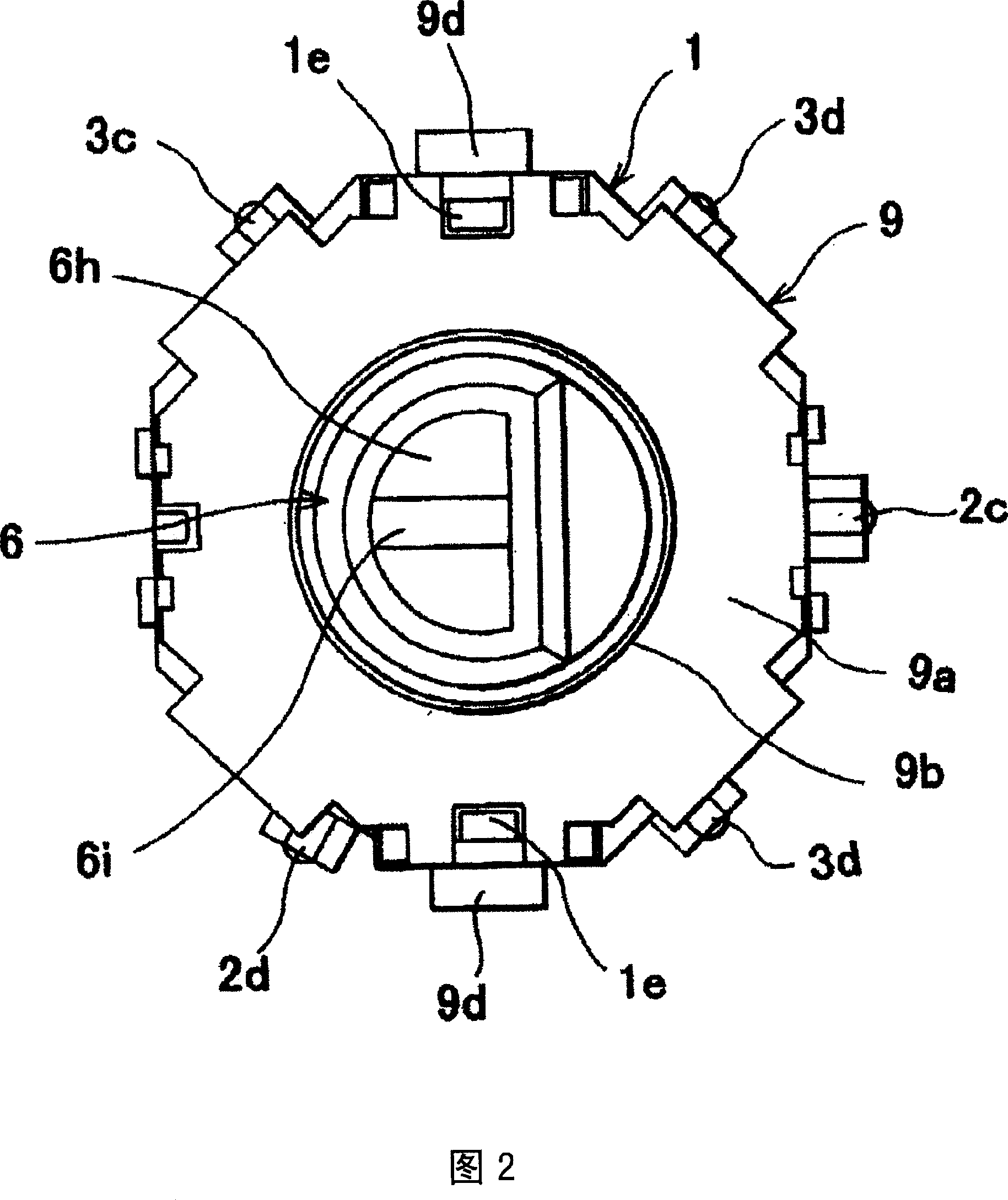
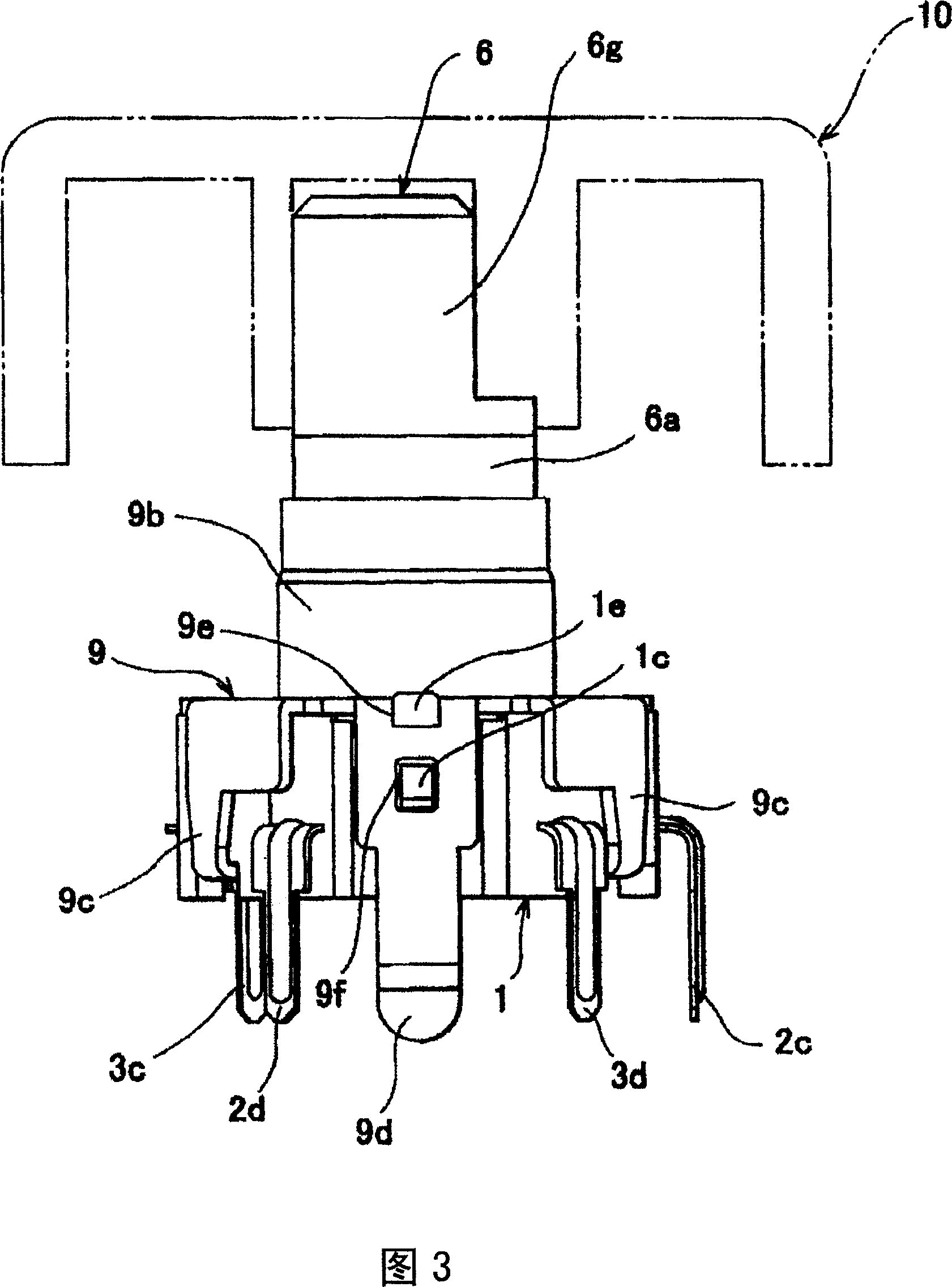
[0048] Shown in Figs. 1 to 16 are embodiments of the present invention. Fig. 1 is an exploded perspective view showing a rotary electric component of the present invention. Fig. 2 is a plan view showing a rotary electric component of the present invention. Fig. 3 is a front view showing a rotary electric component of the present invention. Fig. 4 is a cross-sectional view showing a rotary electric component of the present invention. Fig. 5 is a front view showing the rotating shaft of the rotary electric component of the present invention. Fig. 6 is a left side view of Fig. 5. Fig. 7 is a right side view of Fig. 5. Fig. 8 is a sectional view taken along line 8-8 in Fig. 7 of the present invention. Fig. 9 is a front view showing a rotating body of a rotating electric component of the present invention. Fig. 10 is a right side view of Fig. 9. Fig. 11 is a cross-sectional view taken along line 11-11 in Fig. 10. Fig. 12 is a cross-sectional view taken along line 12-12 in Fig. 10. Fig....


PUM


Abstract

To provide a rotary electric component that cannot be pulled out even if the rotary shaft is pulled with a large force. including a housing having a bearing portion rotatably holding a rotating shaft on which a protruding portion protruding outward in a direction intersecting the axial direction of the rotating shaft is provided, and a rotating body rotating along with the rotation of the rotating shaft, The rotating body is provided with: a central through hole penetrating in the axial direction of the rotating shaft, a through recess continuous with the central through hole and capable of inserting the protruding portion of the rotating shaft, and a center of rotation relative to the through recess and the rotating shaft. An engagement recess with a locking wall at a predetermined angle and on the front side where the rotating shaft protrudes from the bearing to the outside, the rotating shaft is inserted through the central through hole from the front side of the rotating body, and the protrusion is inserted into the through recess, and The rotation shaft is rotated by a predetermined angle, and the protruding portion of the rotation shaft is engaged with the engagement recess in a state capable of locking on the locking wall portion.

Description

Technical field [0001] The present invention relates to a rotary electrical component, and more particularly to a rotary electrical component suitable for a device with a push-button switch. The device with a push-button switch acts on the push-button switch and Pulse switch, etc. to operate. Background technique [0002] As the structure of a rotary electric component in the prior art, a well-known structure includes a push-button switch that opens and closes the switch by the movement of the operating shaft in the axial direction, and the pulse switch or can be turned on and off by the rotation of the operating shaft. Rotary electrical components such as varistors are operated (for example, refer to Patent Document 1). [0003] The structure of this conventional rotary electric component is shown in FIG. 17 and FIG. 18. Fig. 17 is a cross-sectional view of a conventional rotary electric component, and Fig. 18 is an exploded perspective view of a driving body and an operating sh...

Claims


Application Information

Patent Timeline
Patent Type & Authority Applications(China)
IPC IPC(8): H01H25/06
Inventor 沟渕慎一
Owner ALPS ALPINE CO LTD
Learn More