Differential feed dielectric barrier discharging low-temperature plasma device
A technology of dielectric barrier discharge and low-temperature plasma, which is applied in the field of plasma, can solve problems such as prominent insulation problems, increased manufacturing costs, and increased manufacturing difficulties, and achieve the effects of reducing insulation design requirements, improving operational reliability, and reducing volume
- Summary
- Abstract
- Description
- Claims
- Application Information
AI Technical Summary
Problems solved by technology
Method used
Image

Examples
Embodiment 1
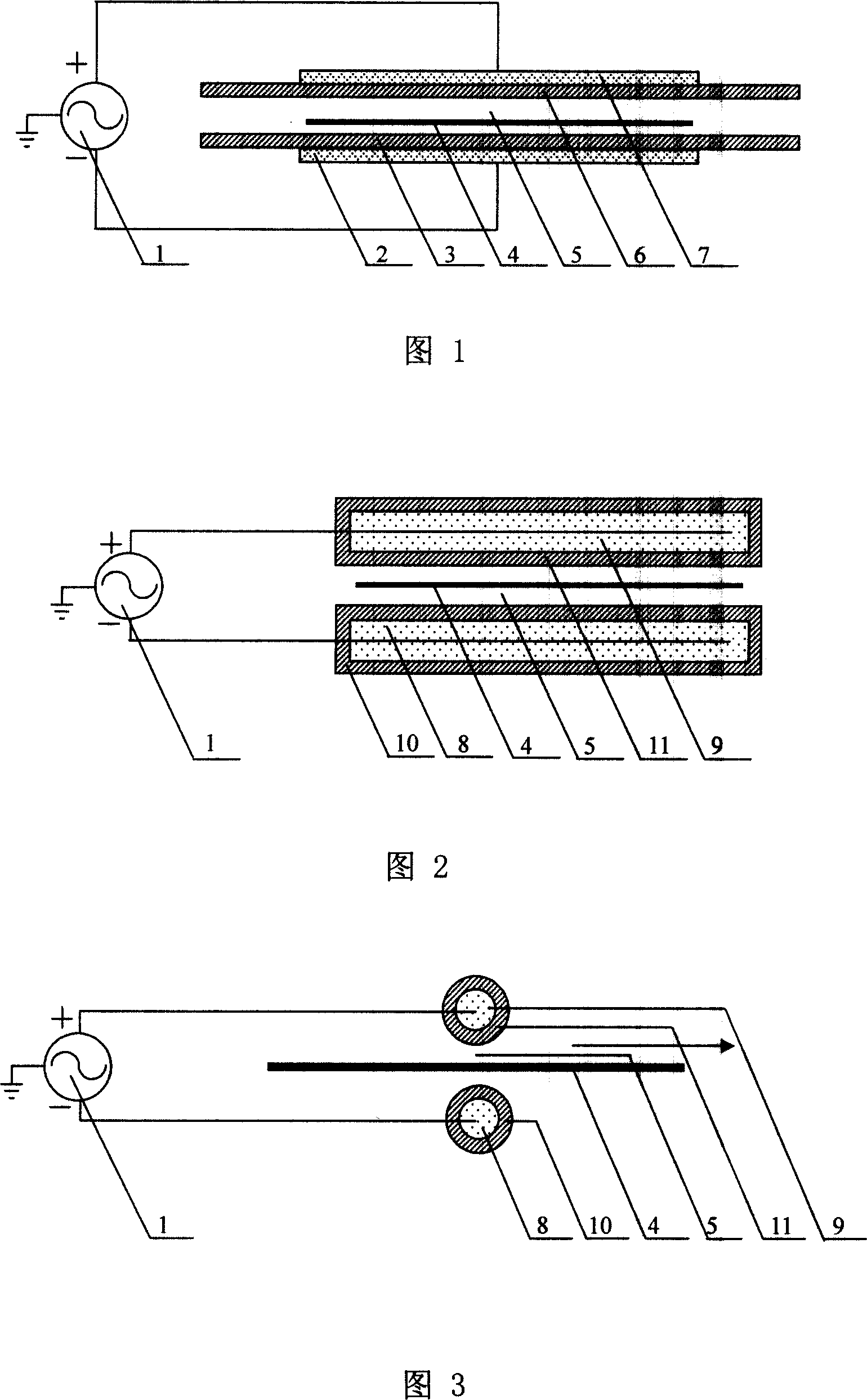
[0031] The differential feed dielectric barrier discharge low-temperature plasma device of this embodiment adopts a parallel flat DBD, and its structure is shown in Figure 1. In this embodiment, both the high-voltage electrode 2 and the high-voltage electrode 7 are metal plates, and the two output terminals of the differential output high-voltage power supply 1 The two output terminals of the differential output high-voltage power supply 1 are connected to the high-voltage electrode 2 and the high-voltage electrode 7 respectively, and the voltage to the ground is equal (or approximately equal), and the phase difference is 180 degrees (or approximately 180 degrees). The surfaces of the high-voltage electrode 2 and the high-voltage electrode 7 are respectively covered with a medium 3 and a medium 6 (the surface of a high-voltage electrode can also be covered with a medium). There is a gas gap 5 between the medium 3 and the medium 6. If the sample is to be processed, the sample 4 can...
Embodiment 2
[0033] The differentially fed dielectric barrier discharge low-temperature plasma device of this embodiment adopts parallel cylindrical electrodes DBD or parallel rectangular electrodes DBD, and its structure is shown in FIG. 2, and FIG. 3 is a schematic side view of FIG. 2. In this embodiment, the high-voltage electrode 8 and the high-voltage electrode 9 can be metal rods, metal particles, metal mesh or other conductive materials (the geometric dimensions of the two high-voltage electrodes can be the same or different), and the surfaces are respectively covered with a medium 10 and a medium 11 (also A high-voltage electrode can be covered with a medium). The two output terminals of the differential output high-voltage power supply 1 are connected to the high-voltage electrodes 8, 9 respectively. The two output terminals of the differential output high-voltage power supply 1 have the same (or approximately the same) voltage to ground and a phase difference of 180 Degree (or approx...
Embodiment 3
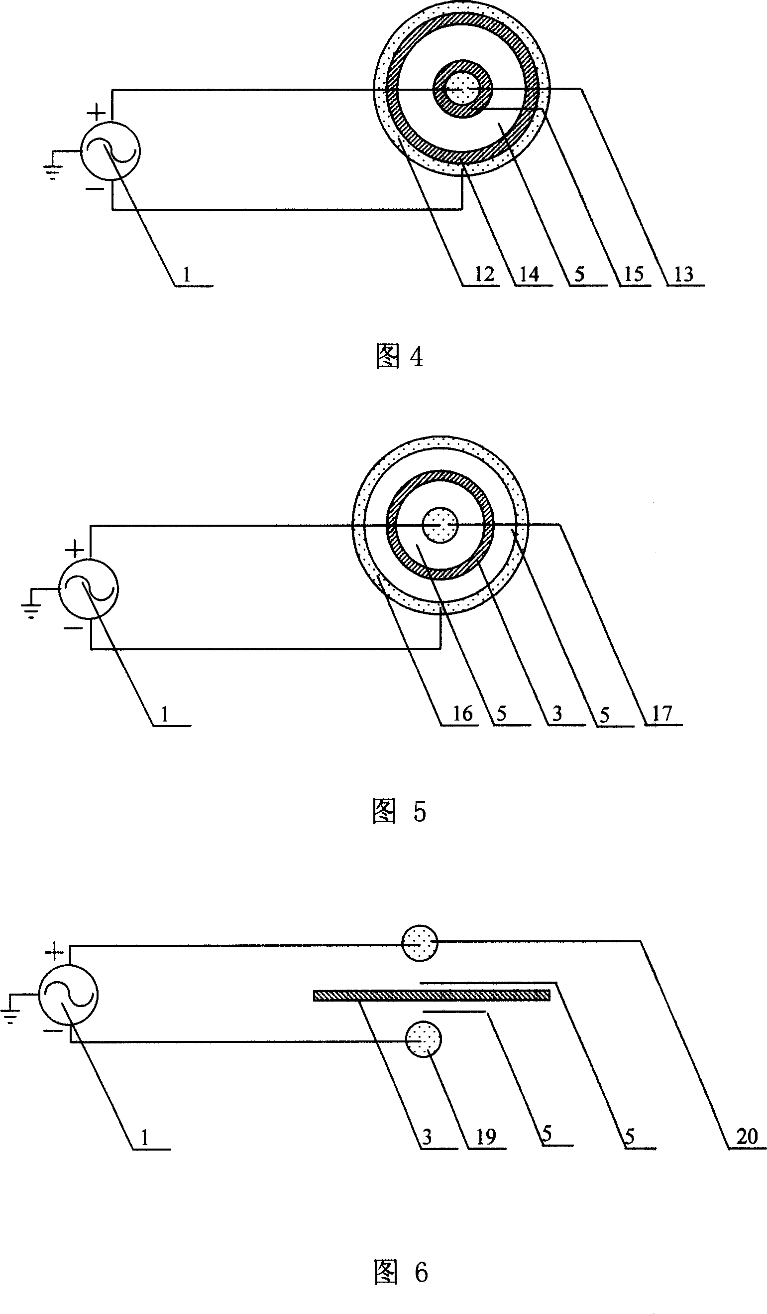
[0035]The differential feed dielectric barrier discharge low-temperature plasma device of this embodiment adopts a coaxial DBD, and its structure is shown in FIG. 4. In this embodiment, the high-voltage electrode 12 is made of metal, and its shape can be a tube, a mesh, or a particle. The high-voltage electrode 13 is a metal, and its shape can be a tube, a rod, a mesh, or a particle. The two output terminals of the differential output high-voltage power supply 1 are connected to the high-voltage electrode 12 and the high-voltage electrode 13, respectively. The two output terminals of the differential output high-voltage power supply 1 have the same (or approximately equal) voltage to the ground, and the phase difference is 180 degrees (or approximately 180 degrees). . The inner wall of the high voltage electrode 12 covers the medium 14, and the outside of the electrode 13 covers the medium 15. There is a gas gap 5 between the medium 14 and the medium 15. The differential output hi...
PUM
 Abstract
Description
Claims
Application Information
 - Generate Ideas
- Intellectual Property
- Life Sciences
- Materials
- Tech Scout
- Unparalleled Data Quality
- Higher Quality Content
- 60% Fewer Hallucinations
Browse by: Latest US Patents, China's latest patents, Technical Efficacy Thesaurus, Application Domain, Technology Topic, Popular Technical Reports.
© 2025 PatSnap. All rights reserved.Legal|Privacy policy|Modern Slavery Act Transparency Statement|Sitemap|About US| Contact US: help@patsnap.com