
LED lamp component circuit unit and compound serial LED lamp circuit

A technology of LED light components and LED light circuits, which is applied in the direction of electric light sources, electrical components, electroluminescent light sources, etc., can solve the problems of low power dissipation, voltage stabilization effect, low reliability, and large power dissipation, and achieve maintenance The maintenance is simple and convenient, the work reliability is improved, and the failure loss is reduced

Inactive Publication Date: 2007-08-15
SHENZHEN UNIBERO TECH
View PDF0 Cites 6 Cited by
  • Summary
  • Abstract
  • Description
  • Claims
  • Application Information

AI Technical Summary

Problems solved by technology

The above-mentioned LED lighting circuit has disadvantages such as complex circuit structure, large current, large power dissipation, low reliability, difficult maintenance, low recycling rate, and high cost, which is not conducive to popularization and promotion. Currently, it is generally only used in decoration, advertising, emergency lighting and other places. use
[0005] For the LED drive circuit, the series LED load has the advantages of small transformation ratio, small output current, low power dissipation, and good voltage stabilization effect. It has always been the preferred circuit structure for LED application development, but the existing series LED load circuit They all use a single LED series connection method. As long as one LED in the series branch is open, the entire LED series branch will not work, or as long as one or more LEDs in the series branch are short-circuited, the remaining LED voltage will drop. Once the circuit breaks down, it is difficult for non-professionals to repair and can only be replaced as a whole
Therefore, this type of LED lighting circuit using a single series LED load also has disadvantages such as poor economical practicability, low reliability, short circuit life, and difficult maintenance, which is not conducive to popularization and application.

Method used


Image

  • LED lamp component circuit unit and compound serial LED lamp circuit
  • LED lamp component circuit unit and compound serial LED lamp circuit

Examples


Embodiment Construction

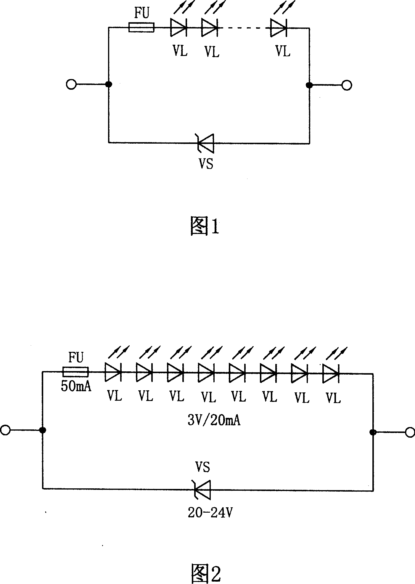
[0028] Fig. 2 is a circuit diagram of a preferred embodiment of the circuit unit of the LED lamp assembly according to the present invention.

[0029] In Figure 2, the rated voltage drop of each LED is 3 volts, the rated current is 20mA, and the rated power is 0.06W. The rated power of 8 LEDs is 0.48W. Take 65% of the rated power to obtain the component circuit unit The rated power of the fuse is about 0.3W; the voltage stabilization value of the Zener diode is selected between 20-24V, and the power is 1W; the current value of the fuse is 50mA.

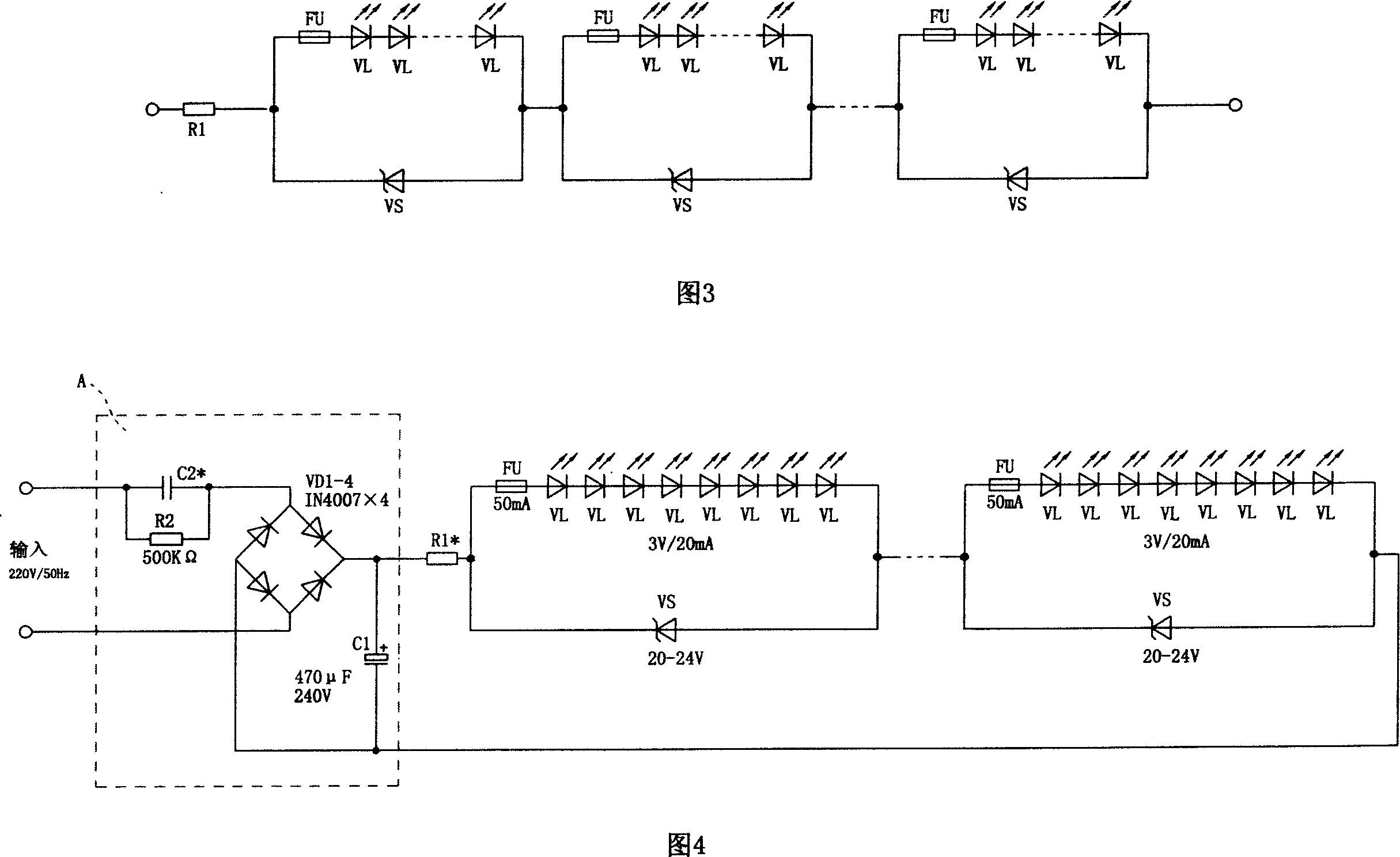
[0030] Fig. 4 is a circuit diagram of a preferred embodiment of an LED lighting circuit composed of a composite series LED lamp circuit according to the present invention.

[0031] In Fig. 4, the composite series LED lamp circuit described in the present invention is connected with the capacitance series transformation type drive circuit A.

[0032] Connected to form a series LED lighting circuit, in the LED series lighting circuit, ...


PUM


Abstract

The related circuit unit of LED lamp assembly comprises: a LED branch with one LED or at least serial two LED's, and a voltage-stabilizing branch with one or at least serial voltage stabilizing diodes. Wherein, it parallels former branches. The composite serial LED lamp circuit comprises at least two of former LED lamp assembly circuit units. Compared with current lighting circuit, this invention improves reliability and maintenance, reduces structure complexity and cost, and overcomes the technical problem applying serial LED load in LED lighting circuit.

Description

technical field [0001] The invention relates to a simple and practical new technology of energy-saving lighting, in particular to a new technology of LED lamp circuit using a new generation of lighting source——LED semiconductor light source. Background technique [0002] In recent years, a new concept of "green lighting" has been proposed in the field of lighting, which means vigorously developing and promoting high-efficiency, energy-saving, environmentally friendly and healthy lighting appliances, eliminating and replacing traditional low-efficiency lighting sources, and saving lighting electricity. At present, in the field of electric lighting technology, from thermal radiation light sources represented by incandescent lamps, to gas discharge light sources represented by fluorescent lamps, to solid-state light-emitting light sources represented by LED semiconductors, LED semiconductor light sources are characterized by their small size and weight. Lightweight, low energy ...

Claims


Application Information

Patent Timeline
Patent Type & Authority Applications(China)
IPC IPC(8): H05B33/08F21V25/00F21Y101/02H05B44/00
CPCY02B20/342H05B33/0821H05B33/0803H05B33/0809H05B45/40Y02B20/30H05B45/34
Inventor 肖祥柏
Owner SHENZHEN UNIBERO TECH
Learn More