
Light source device and projector

A light source device and light source technology, applied to light sources, electric light sources, projection devices, etc., can solve problems such as temperature rise of light source devices, difficulty in cooling light source devices, and failure to achieve long life of light source devices, so as to improve utilization efficiency and degree of freedom Improved effect

Inactive Publication Date: 2007-08-15
SEIKO EPSON CORP
View PDF1 Cites 0 Cited by
  • Summary
  • Abstract
  • Description
  • Claims
  • Application Information

AI Technical Summary

Problems solved by technology

Therefore, there is a problem that the temperature inside the light source device rises, the cooling of the light source device becomes difficult, and the long life of the light source device cannot be achieved.

Method used


Image

  • Light source device and projector
  • Light source device and projector
  • Light source device and projector

Examples


Embodiment Construction

[0047] Hereinafter, an embodiment of the present invention will be described based on the drawings.

[0048] "Projector Composition"

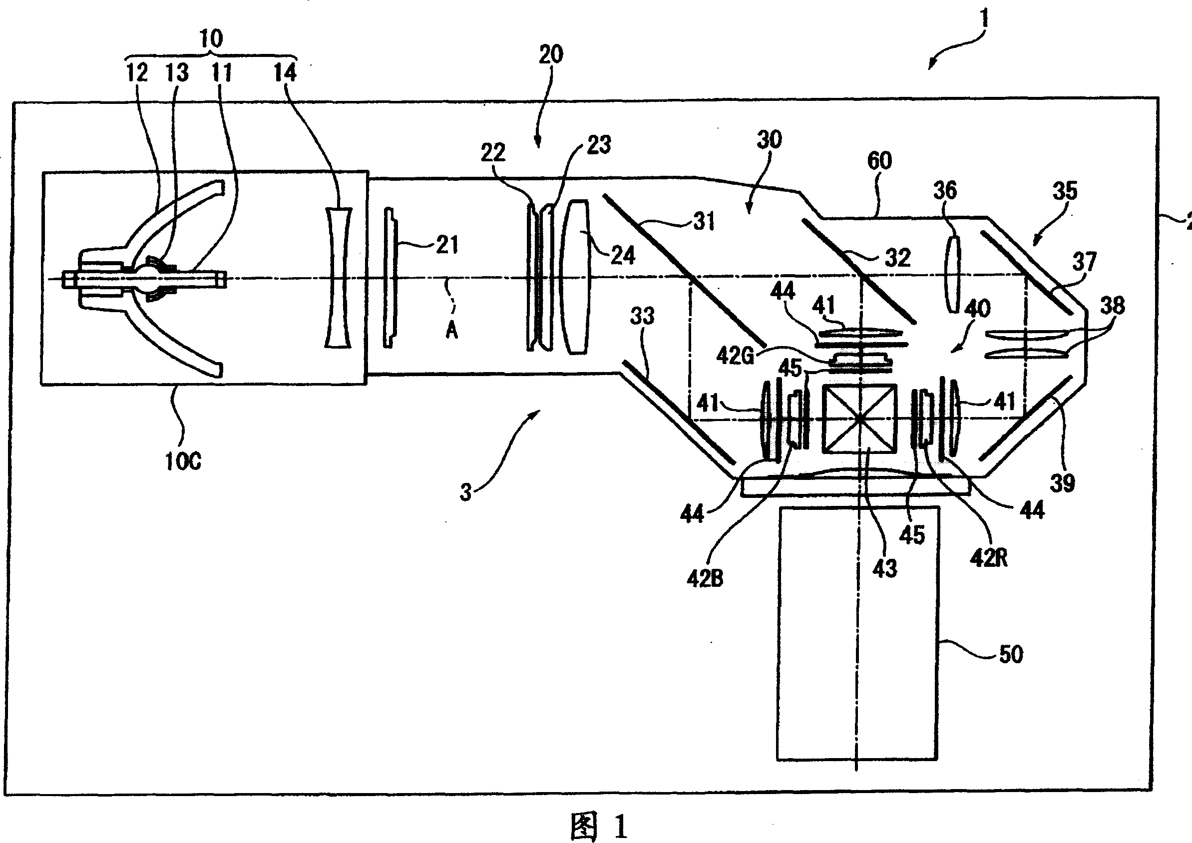
[0049] FIG. 1 is a plan view showing a schematic configuration of a projector 1 in the present embodiment.

[0050] The projector 1 is an optical device that modulates a light beam emitted from a light source according to image information to form image light, and magnifies and projects the image light onto a projection surface such as a screen. As shown in FIG. 1 , the projector 1 is generally composed of a substantially rectangular parallelepiped exterior case 2 and an optical unit 3 housed and arranged inside the exterior case 2 .

[0051] In addition, although specific illustrations are omitted, in the interior of the exterior case 2, in addition to the optical unit 3, a power supply unit for supplying external power to the constituent members of the projector 1 is arranged, and a power supply unit for supplying power to the projector 1 is...


PUM


Abstract

PROBLEM TO BE SOLVED: To provide a light source device and a projector capable of aiming at long life. SOLUTION: The light source device 10 is provided with a light emission tube, a light source lamp 11 having a pair of electrodes arranged in a discharging space of the light emission tube, and a main reflection mirror 12 of which cross section is extended in almost concave-shape, reflecting the light flux emitted from the light source lamp 11. A non-utilized light reflection member 16, having a non-utilized light reflection face 1621, reflecting non-utilized light R3 which is included in the light flux emitted from the light source lamp 11, and coming off from the main reflection mirror 12, is arranged at light emission front side of the main reflection mirror 12. The non-utilized light reflection face 1621 is constituted of an ellipsoid of revolution, of which the position of a first focus F3 is located at central position O of an arc image of the light source lamp 11, reflecting non-utilized light R3 which is emitted from the light source lamp 11 and coming off from the main reflection mirror 12, condensing the non-utilized light on a second focus F4, and guiding it to outside of the light source device 10. COPYRIGHT: (C)2007,JPO&INPIT

Description

technical field [0001] The present invention relates to a light source device and a projector. Background technique [0002] Conventionally, projectors for enlarging and projecting an optical image by modulating a light beam emitted from a light source according to image information have been used. [0003] As a light source device of such a projector, a multi-purpose configuration includes: a discharge type light source lamp such as a metal halide lamp or a high-pressure mercury lamp; a reflector for reflecting a light beam emitted from the light source lamp; A lampshade in which the reflector is accommodated (for example, a document: refer to JP-A-2005-148293). [0004] However, in the light source device described in the literature, among the light beams emitted from the light source lamp, the light beams directed toward the reflector side are reflected by the reflector, and become usable light that can be irradiated to an illumination object. In addition, among the lig...

Claims


Application Information

Patent Timeline
Patent Type & Authority Applications(China)
IPC IPC(8): F21S2/00F21V7/00F21V17/00F21V29/00G03B21/00F21Y101/00
Inventor 山内健太郎桥爪俊明
Owner SEIKO EPSON CORP
Learn More