
Screw lifter

A technology for screw lifts and casings, applied in hoisting devices, hoisting devices, etc., can solve problems such as short life, fatigue cracking, etc.

Inactive Publication Date: 2007-08-15
戴焕平 +1
View PDF0 Cites 2 Cited by
  • Summary
  • Abstract
  • Description
  • Claims
  • Application Information

AI Technical Summary

Problems solved by technology

[0002] In the existing screw elevator structure, the end walls of the upper and lower casings are planes, that is, the end walls intersect the side walls perpendicularly. When the screw elevator is subjected to a pair of pulling forces, the planes of the upper and lower casing end walls will inevitably produce The convex cone is deformed, that is, the vertical angle between the end wall and the side wall is enlarged. In this way, due to the action of the pulse tensile load, repeated deformation occurs at the junction of the plane of the end wall of the casing and the side wall, which is easy to cause fatigue cracking. The actual load test It shows that the existing screw elevator adopts a zinc alloy casing, and its end wall and side wall intersect vertically, that is, the upper and lower casings with a 90° angle. , the upper and lower casings will be fatigued and cracked, and the service life is short

Method used


Image

  • Screw lifter
  • Screw lifter
  • Screw lifter

Examples


Embodiment Construction

[0018] The present invention is described in further detail below in conjunction with the embodiment that accompanying drawing provides.

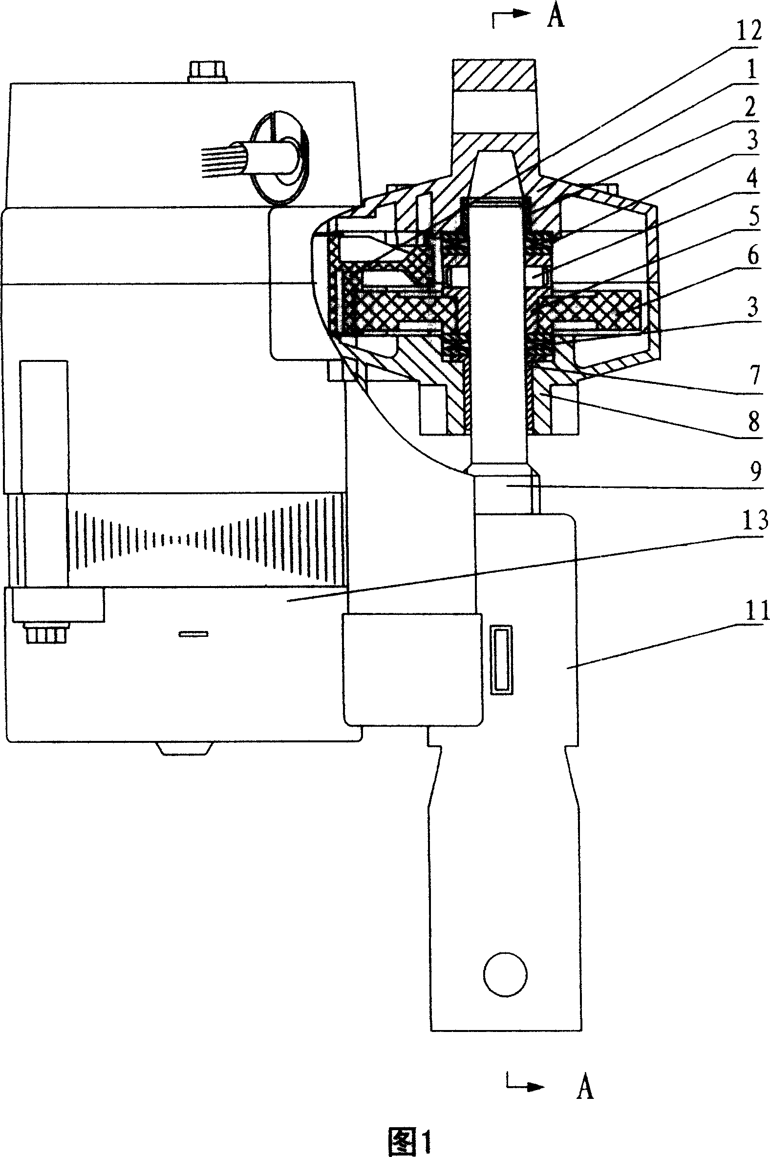
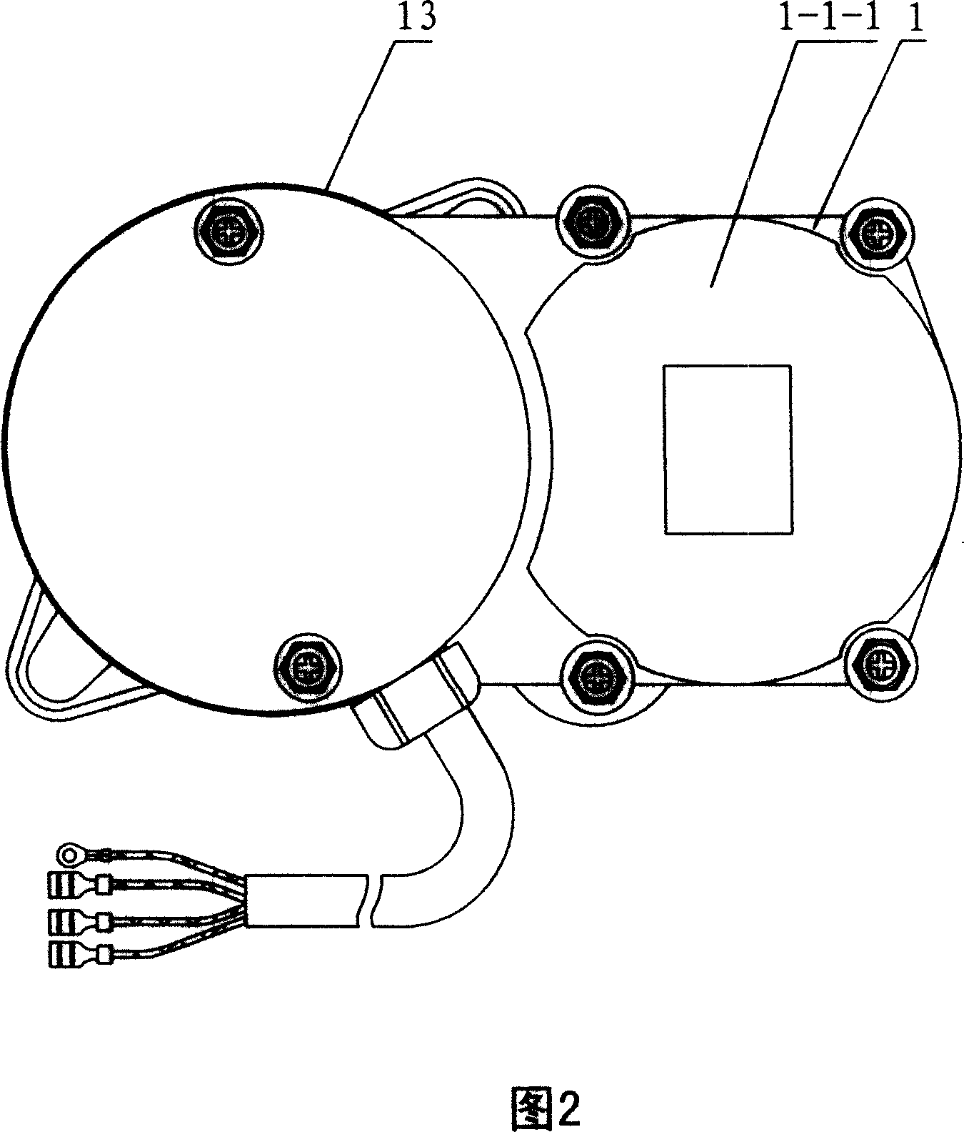
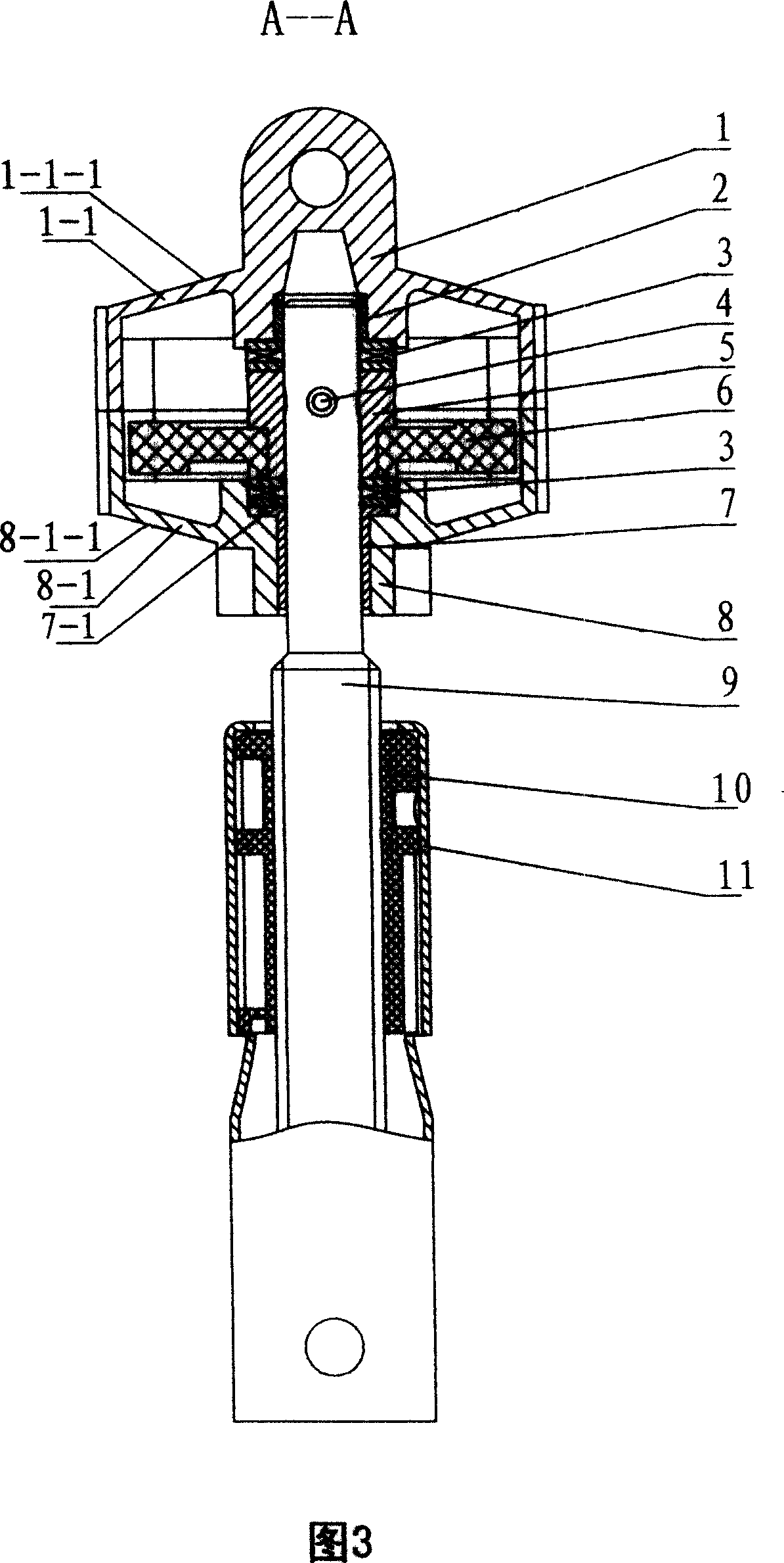
[0019] As shown in Figures 1, 2, and 3, a screw lift of the present invention, a screw lift, includes an upper casing 1, a lower casing 8, a motor 13, a deceleration assembly, bearings 2, 3, 7, and a screw rod 9 and the nut 10, the upper casing 1 and the lower casing 8 are fixedly connected, the motor 13 is connected with the screw rod 9 through the reduction assembly, the screw rod 9 is engaged with the nut 10, and the bearing housing 1 of the upper casing 1 and the lower casing 8- 2. The outer wall surfaces 1-1-1 and 8-1-1 of the housing 1-1 and 8-1 around 8-2 are conically convex. The conical convex outer wall surface 1-1-1, 8-1-1 is a conical convex surface; of course, the conical convex outer wall surface 1-1-1, 8-1-1 can also be a conical convex surface with There are ribs.

[0020] As shown in Figures 1, 3, 9, 10, and 11, in order ...


PUM


Abstract

The invention discloses a screw lifter which can convert rotation into straight motion, comprising an upper case, a lower case, a motor, a speed reducer, a bearing, a lead screw and a nut, wherein the upper and lower cases are fixed, the motor via the speed reducer is geared with the lead screw meshed with a nut, the outer wall of the case around the bearing base of the upper and lower cases is in taper shape whose outer wall can be taper face or taper face disposed with bars. The invention has reasonable force on upper and lower cases, with long service life.

Description

technical field [0001] This invention relates to a device for converting rotation into linear motion, in particular screw jacks. Background technique [0002] In the existing screw elevator structure, the end walls of the upper and lower casings are planes, that is, the end walls intersect the side walls perpendicularly. When the screw elevator is subjected to a pair of pulling forces, the planes of the upper and lower casing end walls will inevitably produce The convex cone is deformed, that is, the vertical angle between the end wall and the side wall is enlarged. In this way, due to the action of the pulse tensile load, repeated deformation occurs at the junction of the plane of the end wall of the casing and the side wall, which is easy to cause fatigue cracking. The actual load test It shows that the existing screw elevator adopts a zinc alloy casing, and its end wall and side wall intersect vertically, that is, the upper and lower casings with a 90° angle. , the upper...

Claims


Application Information

Patent Timeline
IPC IPC(8): B66F19/00
Inventor 杨宗行
Owner 戴焕平
Learn More