Pressure reduction vessel and pressure reduction processing apparatus

A container and internal decompression technology, applied in pressure vessels/vacuum vessels, pressure vessels used in chemical processes, instruments, etc., can solve problems such as difficulty in high-precision machining, increase in the number of manufacturing processes for decompression vessels, and particle generation.

Inactive Publication Date: 2007-07-25
TOKYO ELECTRON LTD
View PDF1 Cites 5 Cited by
  • Summary
  • Abstract
  • Description
  • Claims
  • Application Information

AI Technical Summary

Problems solved by technology

[0008] Although the proposal of the above-mentioned Patent Document 1 is an excellent technology for suppressing particles, in order to have a gap on the joint surface of the two container components, it is necessary to cut either end surface by cutting or the like to provide a step difference, so there are The number of manufacturing steps of the decompression vessel increases, and the larger the vessel, the more difficult it is to perform high-precision machining. Restrictions on processing, etc.
[0009] In addition, in the case of the decompression container of Patent Document 1, since two container components are in direct contact with each other on the outer side of the sealing member, the outer portion is in sliding contact during repeated decompression and atmospheric release. It is also possible to generate particles

Method used


Image

  • Pressure reduction vessel and pressure reduction processing apparatus
  • Pressure reduction vessel and pressure reduction processing apparatus
  • Pressure reduction vessel and pressure reduction processing apparatus

Examples


Embodiment Construction

[0058] Hereinafter, embodiments of the present invention will be specifically described with reference to the drawings.

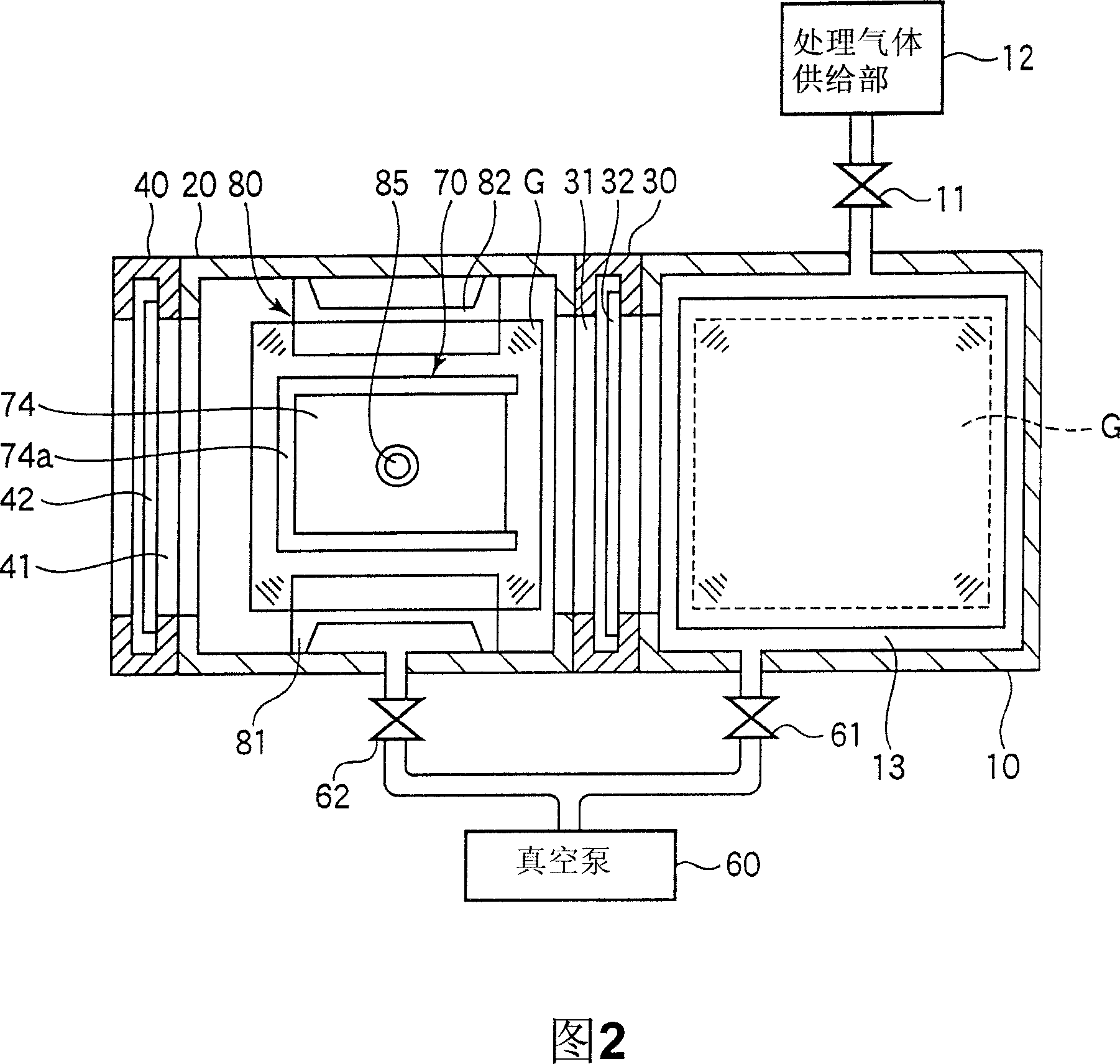
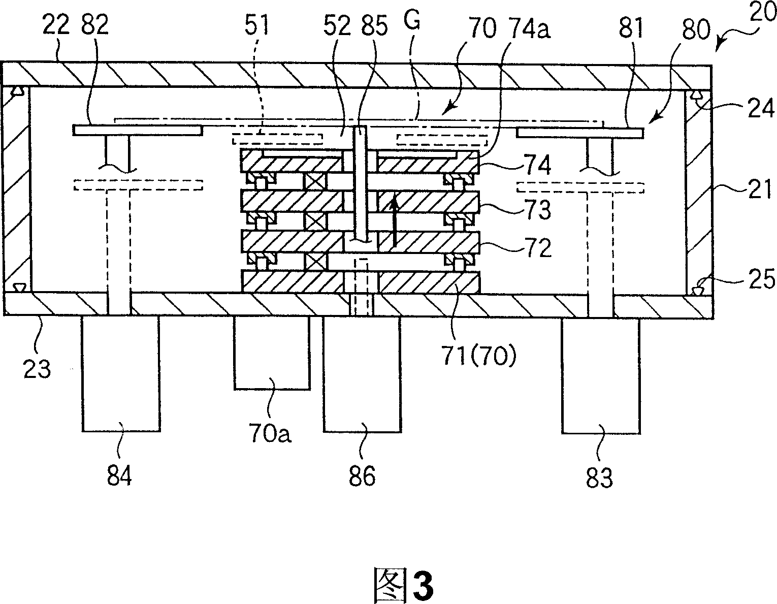
[0059] 1 is a perspective view showing the appearance of a vacuum processing apparatus according to an embodiment of the present invention, FIG. 2 is a horizontal sectional view of the vacuum processing apparatus of FIG. 1 , FIG. 3 is a longitudinal sectional view of a vacuum preparation chamber of the vacuum processing apparatus, and FIG. 4 It is a perspective view showing a configuration example of a substrate transfer mechanism of a substrate transfer device arranged in a vacuum processing chamber.

[0060] The vacuum processing apparatus 100 of this embodiment includes: a vacuum processing chamber 10 for performing desired vacuum processing such as plasma etching processing and thin film forming processing on a substrate G such as an LCD glass substrate under a vacuum atmosphere; , the load lock chamber 20 functioning as a vacuum preparation chamber; th...


PUM

PropertyMeasurementUnit
Shore hardnessaaaaaaaaaa

Abstract

The present invention provides a pressure reduction vessel and a pressure reduction processing apparatus which can prevent the grain generated by distortion of the vessel. A O-shape ring (90) is inserted into a groove (26) on the top end surface (21a) of the vessel main body (21) formed in the inner space enclosing a load locking chamber (20) as a sealing component, outside of the ring, a L-shape section shape pad (91) is partly inserted into the groove (26) and the inner angle side surface of the L-shape is partly contacted to the place between the inner wall surface of the groove (26) and the top end surface (21a) of the vessel main body (21). The vessel main body (21) is separated from the top plate (22) by the pad (91), therefore, even the inside of the load locking chamber (20) is reduced to high vacuum status, the top plate (22) generates bending, the angle part (21b) of the inner circumferential side of the vessel main body (21) can be prevented from contacting with the top plate (22).

Description

technical field [0001] The present invention relates to a decompression container and a decompression treatment device, and in particular to a device suitable for performing dry etching, film formation, and transportation of glass substrates for flat panel displays (FPDs) such as liquid crystal display devices (LCDs) and plasma displays under reduced pressure. Technology for decompression vessels and decompression treatment devices used for decompression treatment such as , positioning, etc. Background technique [0002] For example, in the LCD manufacturing process, dry etching, sputtering, and CVD (Chemical Vapor Growth) and other reduced-pressure treatments are often used for LCD glass substrates as substrates to be processed. [0003] In the decompression processing apparatus for performing such decompression processing, a vacuum preparation chamber is provided, which is kept in a decompressed state, such as in a vacuum, and is adjacent to the vacuum processing chamber f...

Claims


Application Information

Patent Timeline
Patent Type & Authority Applications(China)
IPC IPC(8): H01L21/00C23C14/56C23C16/44C23F4/00B01J3/03
CPCC23C14/56G02F1/1303H01J2237/0225H01L21/67126H01L21/67248
Inventor 山田洋平
Owner TOKYO ELECTRON LTD
Why Eureka
Try Eureka