Apparatus for fabricating optical fiber preform and method for fabricating low water peak fiber using the same

An optical fiber preform and preform technology, which can be applied to manufacturing tools, glass manufacturing equipment, etc., can solve the problems of manufacturing cost and time of elongating the first optical fiber preform.

Inactive Publication Date: 2007-07-18
SAMSUNG ELECTRONICS CO LTD
View PDF0 Cites 5 Cited by
  • Summary
  • Abstract
  • Description
  • Claims
  • Application Information

AI Technical Summary

Problems solved by technology

However, in this case, there is a problem that the manufacturing cost and time of the elongated first optical fiber preform increase

Method used


Image

  • Apparatus for fabricating optical fiber preform and method for fabricating low water peak fiber using the same
  • Apparatus for fabricating optical fiber preform and method for fabricating low water peak fiber using the same
  • Apparatus for fabricating optical fiber preform and method for fabricating low water peak fiber using the same

Examples


Embodiment Construction

[0030] Embodiments of the present invention are described below with reference to the drawings. For clarity and simplicity, detailed descriptions of well-known functions and constructions incorporated herein are omitted to avoid obscuring the subject matter of the present invention.

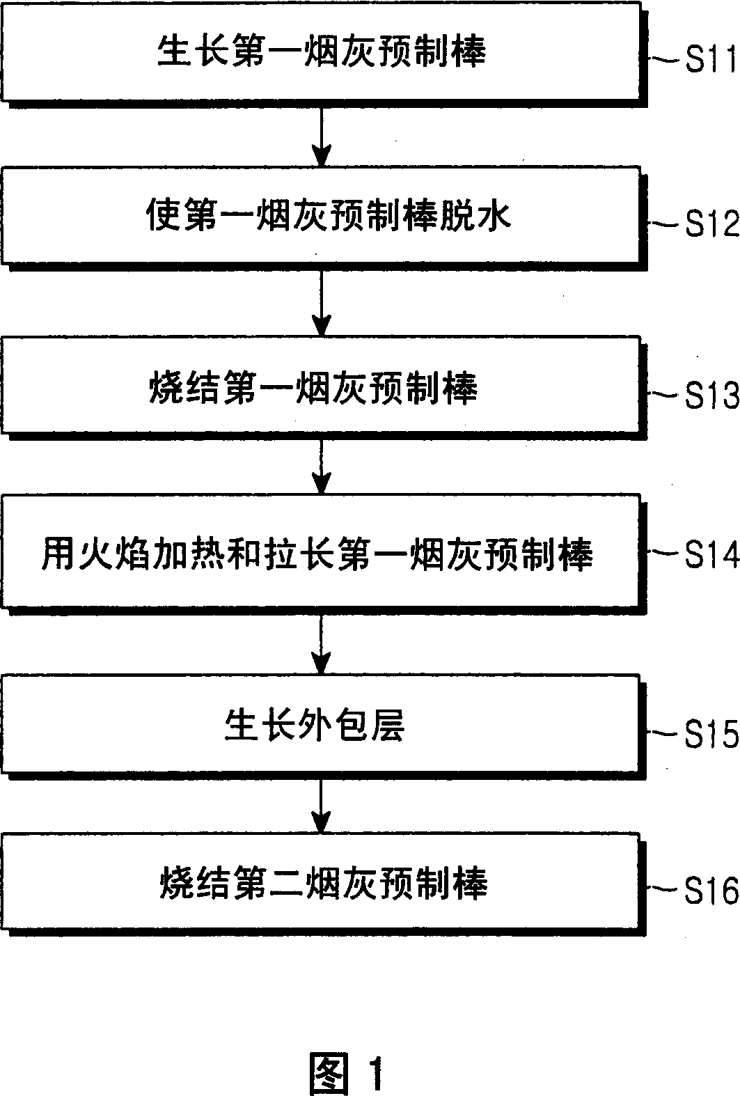
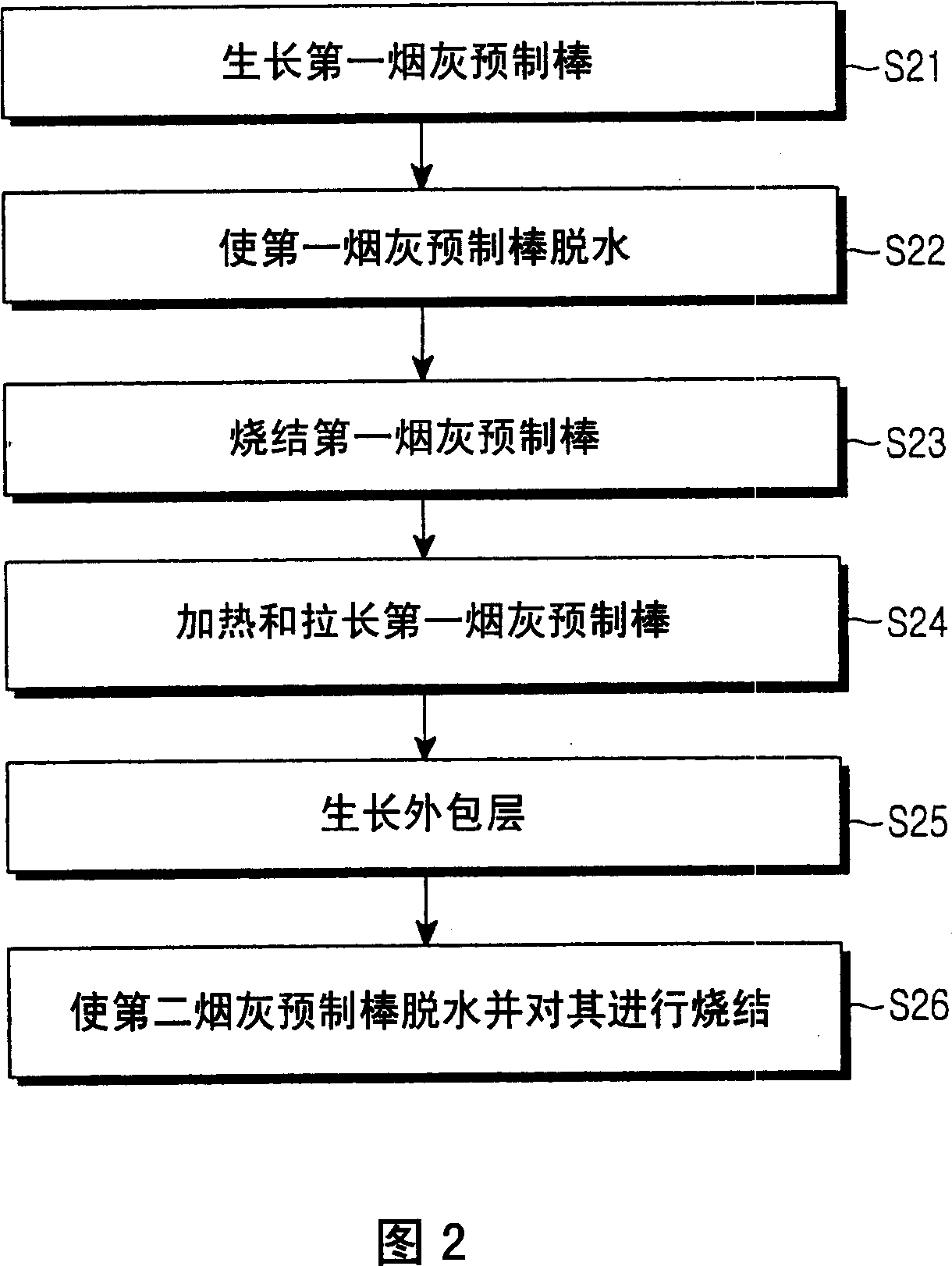
[0031] FIG. 2 is a flowchart illustrating an optical fiber preform manufacturing method according to a preferred embodiment of the present invention, and FIGS. 3 to 12 are views illustrating its steps for manufacturing an optical fiber preform. The method for manufacturing an optical fiber preform includes steps (a), (b), (c), (d), (e) and (f): S21 , S22 , S23 , S24 , S25 and S26 in FIG. 2 .

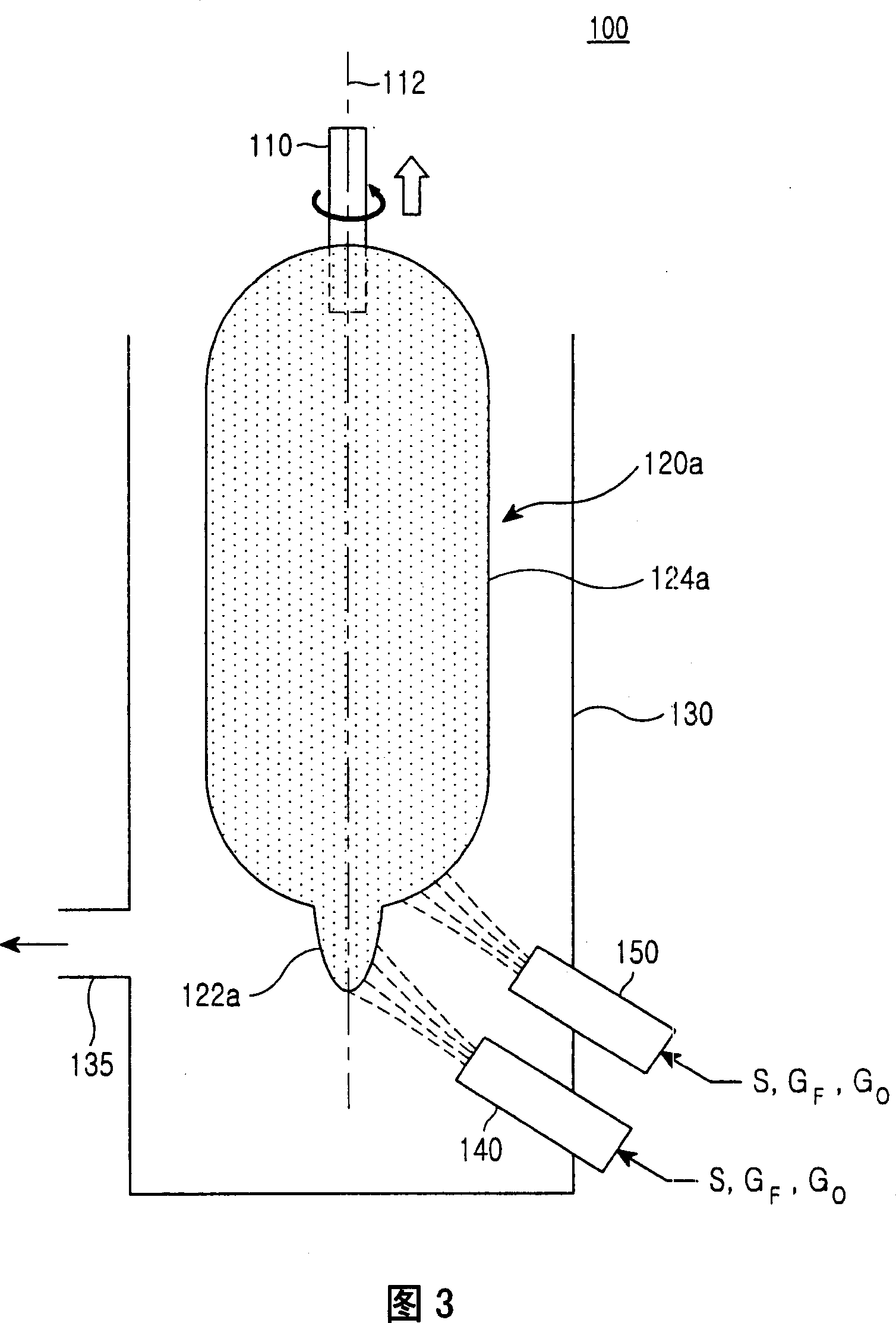
[0032] Step (a) S21 is a process of growing a first soot preform on the starting member along the longitudinal direction of the starting member by soot deposition.

[0033] FIG. 3 is a view illustrating step (a) S21 of growing the first soot preform. The apparatus 100 for manufacturing an optical fiber pr...


PUM


Abstract

Disclosed is a method for fabricating an optical fiber preform. The method includes: (a) growing a first soot preform on a starting member along a lengthwise direction of the starting member by a soot deposition; (b) dehydrating the first soot preform; (c) sintering the dehydrated first soot preform, to obtain a first glassed optical preform; and (d) elongating the first optical fiber preform by heating the first optical fiber with a heat source that excludes hydrogen, wherein the first glassed optical fiber is elongated by means of only a heat source that excludes the use of hydrogen.

Description

technical field [0001] The present invention relates to optical fiber preforms, and more particularly, the present invention relates to methods of making optical fiber preforms using soot deposition and methods of making low water peak optical fibers. Background technique [0002] Known methods of fabricating optical fiber preforms include Modified Chemical Vapor Deposition (MCVD), Vapor Axial Deposition (VAD), Outside Vapor Deposition (OVD), Plasma Chemical Vapor Deposition (PCVD), and the like. [0003] In the vapor phase axial deposition method, source materials, fuel gas, and the like are supplied to a burner, whereby soot is generated by flame hydrolysis. The resulting soot is then deposited on the starting components. The soot preform further grows from the end of the starting member along the longitudinal direction of the starting member. [0004] Fig. 1 is a flowchart illustrating a conventional manufacturing method of an optical fiber preform. The method includes...

Claims


Application Information

Patent Timeline
Patent Type & Authority Applications(China)
IPC IPC(8): C03B37/018
CPCC03B37/01466C03B37/01446
Inventor 尹暎植都文显金镇杏
Owner SAMSUNG ELECTRONICS CO LTD
Why Eureka
Try Eureka