
Lumber slicer

A chip splitter and log technology, applied in the manufacture of thin wood chips, wood processing equipment, manufacturing tools, etc., can solve the problems of unprocessable logs, poor working environment, etc., achieve wood saving, high production efficiency, and reduce labor The effect of intensity

Inactive Publication Date: 2007-07-18
冯士祥
View PDF1 Cites 4 Cited by
  • Summary
  • Abstract
  • Description
  • Claims
  • Application Information

AI Technical Summary

Problems solved by technology

With such a structure, the log is clamped by the clamping platform mechanism, and the clamping platform mechanism reciprocates to complete the opening of the log. The larger noise and flying sawdust during processing cause a poor working environment. The band saw can only be used in one The band saw works in the opposite direction, and the band saw does not work in the opposite direction, and cannot process long logs

Method used


Image

  • Lumber slicer
  • Lumber slicer
  • Lumber slicer

Examples


Embodiment Construction

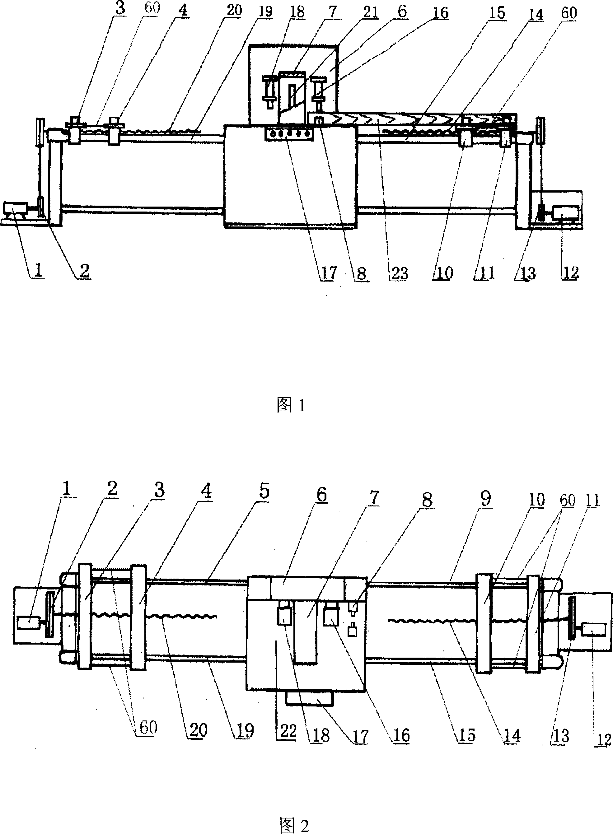
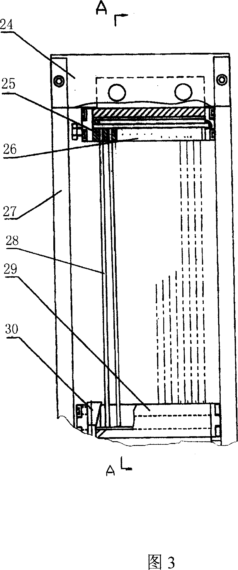
[0026] As shown in Fig. 1 and Fig. 2, the round log frame sawing machine that can directly process the round wood into slices includes a frame saw in the middle of the working platform 22 of the frame, the power mechanism, and the working platform 22 of the frame 6. The opening through which the mechanism 21 passes, there is a wood support mechanism 18 above the two sides of the frame saw mechanism 21, and the two sides of the working platform 22 are fixedly connected with a feed mechanism that pushes the log to the frame saw at a uniform speed and a feed mechanism that pushes the log to the frame saw at a uniform speed. Pull off the catch mechanism of the frame saw. There is a log centering mechanism 8 in front of the feeding of the frame saw mechanism 21, and the frame 6 above the working platform 22 has a rectangular frame 7, and the frame saw mechanism 21 reciprocates up and down in the rectangular frame 7, and the log 23 The axis is perpendicular to the frame saw mechanis...


PUM


Abstract

The present invention discloses a log slitting machine. It includes the following several portions: machine frame, power mechanism, working platform, feeding mechanism, saw-cutting mechanism and discharging mechanism.

Description

technical field [0001] The invention relates to a wood processing machine, in particular to a log splitter. Background technique [0002] The current log splitters are only suitable for square logs. In the process of processing, at least three sides of the logs need to be cut into shapes perpendicular to each other. In the 1990s, improving the utilization rate of wood became an effective means to solve the shortage of wood resources. The Chinese Patent Publication No. CN2582830 is a utility model patent, which discloses an automatic cutting machine for log band saws, including a frame, a speed-regulating motor, a gearbox, a wood clamping platform mechanism, a wood chip splitting mechanism, and a wood chip splitting mechanism. And the transmission mechanism that pushes the clamping platform mechanism for horizontal reciprocating movement. The wood chip slicing mechanism is installed on the gantry tool holder of the frame. The lifting platform is threaded on the lifting scre...

Claims


Application Information

Patent Timeline
Patent Type & Authority Applications(China)
IPC IPC(8): B27L5/06
Inventor 冯士祥
Owner 冯士祥
Learn More