Automatic mounting or dismounting automobile anti-skid chain
An anti-skid chain, automobile technology, applied in anti-skid devices, vehicle parts, transportation and packaging, etc., can solve the problems of affecting vehicle speed, poor reliability, short life, etc., and achieve the effect of improving driving speed, wide application model and reliable performance.
- Summary
- Abstract
- Description
- Claims
- Application Information
AI Technical Summary
Problems solved by technology
Method used
Image
Examples
Embodiment 1
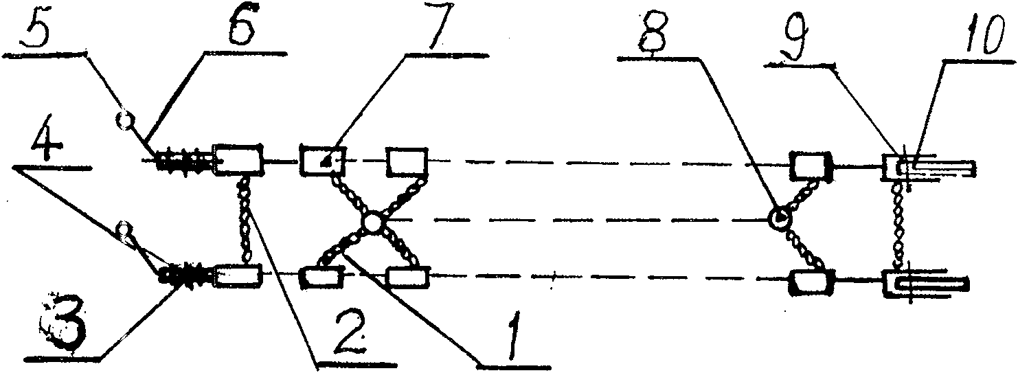
[0040] Embodiment 1: by figure 1It can be seen that the chain includes an oblique main chain 1, a straight main chain 2, an adjusting piece 3, an adjusting piece pin 4, a steel ball 5, a tie rod 6, a secondary chain link 7, a connecting ring 8, a pin 9, and a quick clip 10. The inclined main chain 1 is a twist chain, one end is connected with the secondary chain link 7, and the other end is connected with the coupling ring 8. The straight main chain 2 is also a twist chain, and the two ends are connected with the secondary chain links 7 on both sides. There are two adjusting pieces 3 on both sides of one end of the chain, connected with several adjusting piece pins 4 between the two adjusting pieces, the end of the adjusting piece 3 connects the pull bar 6, and the end of the pull bar 6 connects the steel ball 5. The pin shaft 9 of the auxiliary chain link 7 at the other end of the chain is connected with the quick clip 10 . Along with the wearing and tearing of tire, tire s...
Embodiment 2
[0052] Embodiment 2: by Figure 11 It can be seen that the transmission line of the gearbox 55 is driven by a single motor. Namely motor 48, worm and worm gear pair 67, electromagnetic clutch 69, rack and pinion pair 66 realize the linear reciprocating motion of gearbox drum assembly;
[0053] Depend on Figure 15It can be seen that the method for setting the system safety signal is to install a hemispherical iron plate 87 on the side plate of the drum 40, and connect the pin shaft 88, which is connected to the push rod 89, and the end of the push rod is fixed with an induction sheet, and is mounted on the drum bracket. The corresponding position is installed with induction element 90. A roller hook with a quick clip is pulled into the roller groove when the roller rotates, and when it touches the iron plate 87, the push pin shaft 88 and the push rod 89 move to the left, and the proximity sensing element 90 generates a signal. If there is only one, there is no signal, and t...
PUM
 Abstract
Description
Claims
Application Information
 - Generate Ideas
- Intellectual Property
- Life Sciences
- Materials
- Tech Scout
- Unparalleled Data Quality
- Higher Quality Content
- 60% Fewer Hallucinations
Browse by: Latest US Patents, China's latest patents, Technical Efficacy Thesaurus, Application Domain, Technology Topic, Popular Technical Reports.
© 2025 PatSnap. All rights reserved.Legal|Privacy policy|Modern Slavery Act Transparency Statement|Sitemap|About US| Contact US: help@patsnap.com


