
Optical fiber sampling optical grating and planar optical wave guide sumpling grating

A technology of sampling gratings and planar waveguides, applied in the coupling of optical waveguides, optical guides, optics, etc., can solve problems such as errors and 1ps delay difficulties, and achieve the effect of satisfying integration

Inactive Publication Date: 2009-12-23
SHENZHEN INST OF ADVANCED TECH
View PDF3 Cites 0 Cited by
  • Summary
  • Abstract
  • Description
  • Claims
  • Application Information

AI Technical Summary

Problems solved by technology

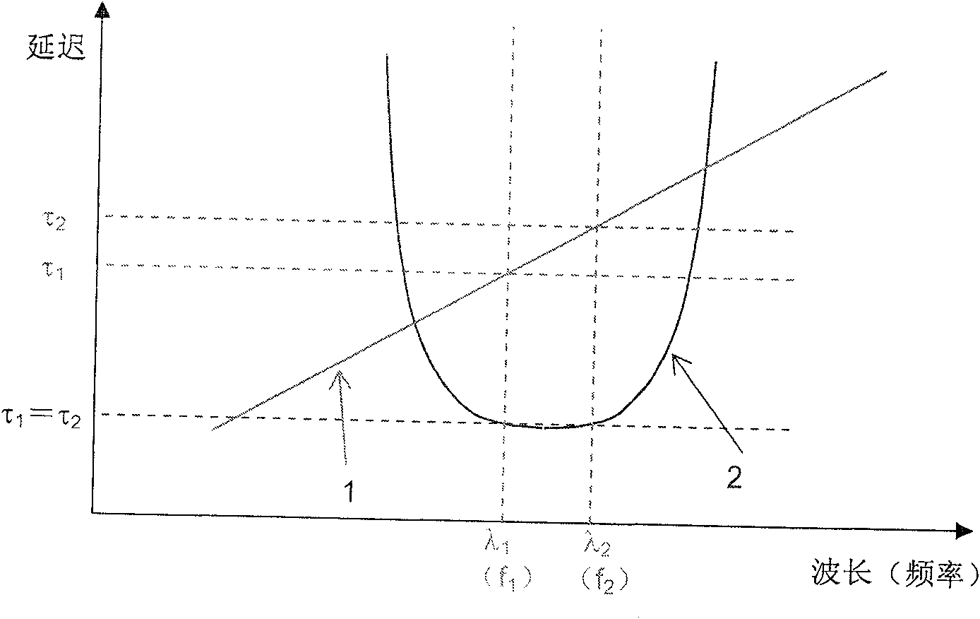
Since 1ps corresponds to a fiber length of 0.2mm, writing gratings each time may cause errors caused by adjustments, so when the number of gratings to be written is large, this problem is more serious, so superimposed gratings write gratings multiple times Manufacturing characteristics determine that it is difficult to achieve a large and constant 1ps delay with this method

Method used


Image

  • Optical fiber sampling optical grating and planar optical wave guide sumpling grating
  • Optical fiber sampling optical grating and planar optical wave guide sumpling grating
  • Optical fiber sampling optical grating and planar optical wave guide sumpling grating

Examples


Embodiment Construction

[0033] Below according to accompanying drawing and embodiment the present invention will be described in further detail:

[0034] The sampling grating that can generate a constant time delay of less than 1 ps according to the present invention can be formed on an optical fiber or on a planar optical waveguide, because the planar optical waveguide can produce a larger relative refractive index change relative to the optical fiber core, In this way, more high-reflectivity wavelength channels that meet the requirements of the special delay spectrum envelope can be obtained, and the Sinc formed on the planar optical waveguide 2 The sampling grating can be integrated with other devices in a planar light wave circuit. Since the principles and methods of forming sampling gratings on optical fibers and planar waveguides are the same, the following analysis will only take sampling gratings produced on planar waveguides as an example.

[0035] A fiber grating is an optical wavelength s...


PUM


Abstract

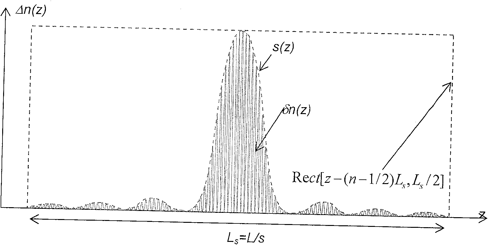
An optical fiber sampling grating and a planar optical waveguide sampling grating, the refractive index of the grating along the core / waveguide axis is periodically distributed, and is represented by the product of the refractive index function and the sampling function of the mother grating; the mother grating The refractive index function is δn(z)=δn0Sin〔4πnez / λB〕, wherein: δn0 is the refractive index variation range of the grating, ne is the effective refractive index of the fiber core / waveguide, and λB is the Bragg wavelength of the grating; the sampling function The Fourier transform has the characteristics of bilateral symmetry and linear or approximately linear change, using functions such as Sinc2, second-order rational functions or Sinc-Sinc2 combination functions. The Sinc2 sampling fiber grating and Sinc2 sampling planar waveguide grating have a linear or approximately linear delay spectrum envelope, and each wavelength channel is symmetrical, can produce a large number of constant delay steps less than 1ps and can allow signal broadband work .

Description

technical field [0001] The invention relates to a photon element, in particular to a fiber sampling grating and a planar optical waveguide sampling grating used as a high-resolution and high-speed signal processor. Background technique [0002] In many cases of communication, signals take different times to travel through different channel media and exhibit different delays (delay is a relative relationship in time) when reaching the next receiver or processor. ps(10 -12 Seconds) short delays have many important applications, such as high-resolution delayed signal processing in microwave phased array beamforming. THz optical sampling is generated by means of multi-wavelength light sources, thereby realizing many high-speed and broadband signal processing functions. Traditional electronic delay lines are only capable of generating ns(10 -9 second) level of short delay, and cannot work in broadband due to frequency dependence. The general fiber delay line overcomes the dif...

Claims


Application Information

Patent Timeline
Patent Type & Authority Patents(China)
IPC IPC(8): G02B6/124G02B6/293G02B6/34
Inventor 沈明亚
Owner SHENZHEN INST OF ADVANCED TECH
Learn More