Radiation photography device
A photographic device, radiation technology, applied in the fields of radiological diagnostic equipment, medical science, diagnosis, etc., can solve problems such as insufficient research, and achieve the effect of excellent contrast
- Summary
- Abstract
- Description
- Claims
- Application Information
AI Technical Summary
Problems solved by technology
Method used
Image
Examples
no. 1 Embodiment approach
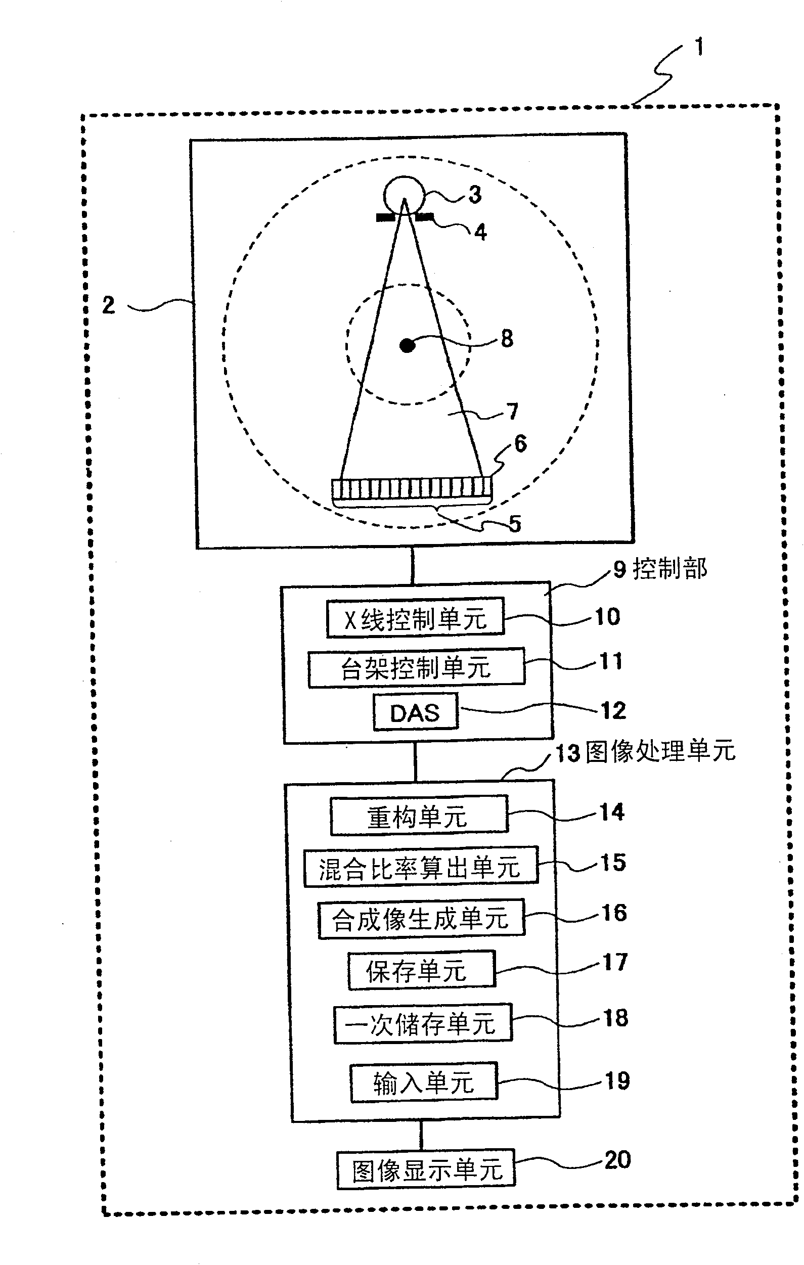
[0057] figure 1 It is a diagram showing a preferred embodiment of the radiographic apparatus (hereinafter referred to as "X-ray CT apparatus") of the present invention. The X-ray CT apparatus 1 of the present invention includes a gantry 2 , and the gantry 2 has an X-ray source 3 , a collimator 4 and a detector array 5 located on the opposite surface of the gantry 2 . The detector array 5 is formed of detector elements 6 that detect X-rays transmitted through a subject on a pedestal (not shown). The detector elements 6 are arranged in a row shape, or a plurality of rows arranged side by side. Each detector element 6 generates an electrical signal indicating the intensity of the incident X-ray beam, that is, the attenuation of the X-ray beam when it passes through the subject. X-ray projection data can be acquired by rotating the gantry 2 around the rotation center 8 while the X-rays 7 are irradiated from the X-ray source 3 . The gantry 2 and the X-ray source 3 are controlled...
no. 2 Embodiment approach
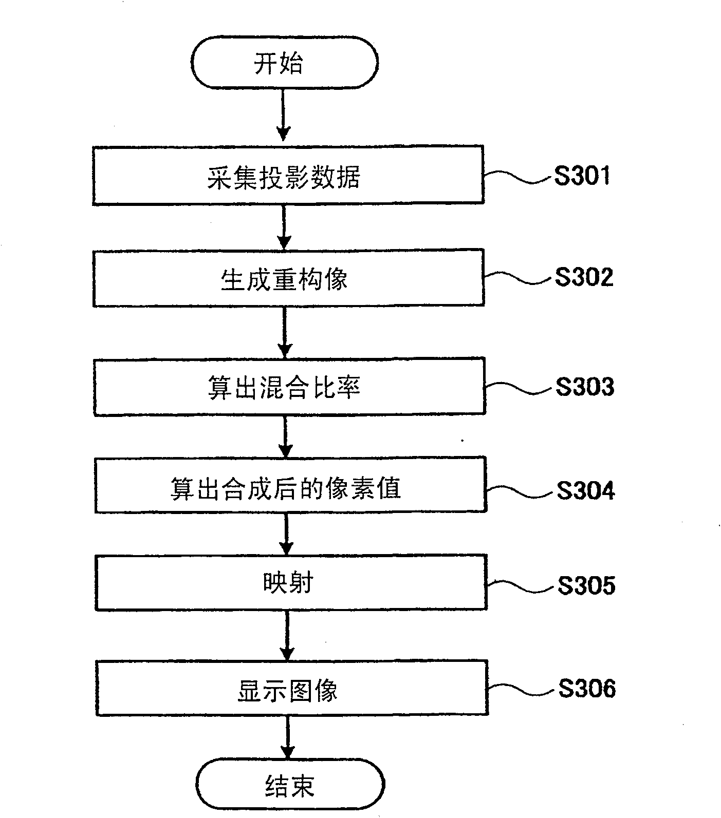
[0076] Figure 5 This is the flow of processing from acquisition of projection data to display of composite images in the second embodiment of the X-ray CT apparatus of the present invention.
[0077] In step S501, first collect projection data (S501). The method for collecting data may be the same as that of the first embodiment.
[0078]In step S502, the reconstruction unit 14 generates a first reconstructed image and a second reconstructed image for the projection data of each energy spectrum (S502).
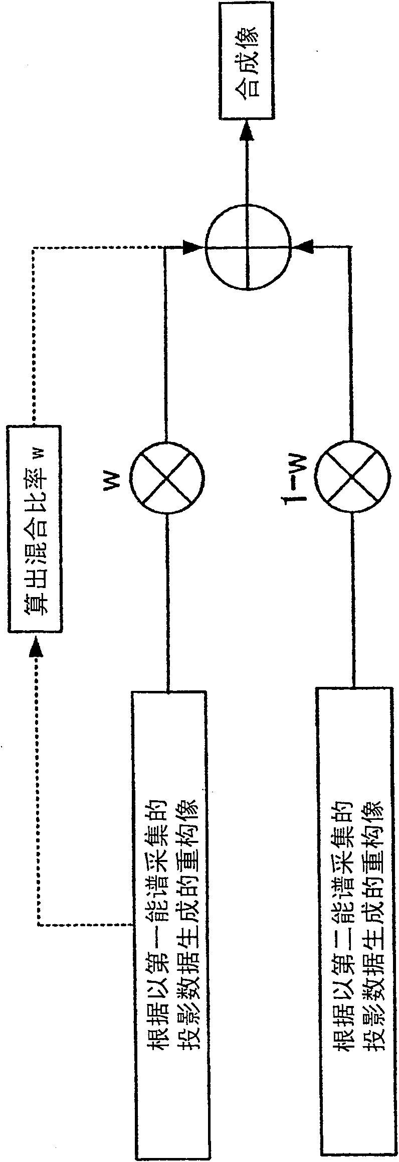
[0079] In step S503, the mixing ratio calculation unit 15 calculates the effective atomic number of the pixel or local area of interest (S503). The mixing ratio calculation unit 15 segments the first reconstructed image and the second reconstructed image by tissues having the same biological function. In multi-energy CT, instead of obtaining the overall attenuation coefficient as in conventional CT, a pair of images representing the respective attenuations from contrast ...
no. 3 Embodiment approach
[0090] Figure 7 This is the processing flow from the acquisition of projection data to the display of the composite image in the third embodiment of the X-ray CT apparatus of the present invention.
[0091] In step S701, projection data is first acquired (S701). The method of data collection may be the same as that of the first embodiment and the second embodiment.
[0092] In step S702, the reconstruction unit 14 generates a first reconstructed image and a second reconstructed image for the projection data of each energy spectrum (S702).
[0093] In step S703, the mixing ratio calculation unit 15 calculates the local standard deviation of the pixel values around the pixel of interest, or the local standard deviation of the local area (S703).
[0094] In step S704, the mixing ratio calculation unit 15 compares the local standard deviation (SD1) of the first reconstructed image generated from the projection data acquired by the first energy spectrum and the projection data...
PUM
 Abstract
Description
Claims
Application Information
 - Generate Ideas
- Intellectual Property
- Life Sciences
- Materials
- Tech Scout
- Unparalleled Data Quality
- Higher Quality Content
- 60% Fewer Hallucinations
Browse by: Latest US Patents, China's latest patents, Technical Efficacy Thesaurus, Application Domain, Technology Topic, Popular Technical Reports.
© 2025 PatSnap. All rights reserved.Legal|Privacy policy|Modern Slavery Act Transparency Statement|Sitemap|About US| Contact US: help@patsnap.com


