
Terminal conveyor

A technology of conveying devices and terminals, which is applied in the direction of conveyors, conveyor objects, mechanical conveyors, etc., and can solve the problem that terminals cannot enter.

Inactive Publication Date: 2009-12-02
李莉宏
View PDF5 Cites 0 Cited by
  • Summary
  • Abstract
  • Description
  • Claims
  • Application Information

AI Technical Summary

Problems solved by technology

[0007] The object of the present invention is to provide a terminal conveying device for the defects of the above-mentioned prior art, which can prevent the terminals from being stuck in the conveying device and prevent the terminals from entering the conveying mechanism of the conveying device due to mechanical vibration.

Method used


Image

  • Terminal conveyor
  • Terminal conveyor
  • Terminal conveyor

Examples


Embodiment Construction

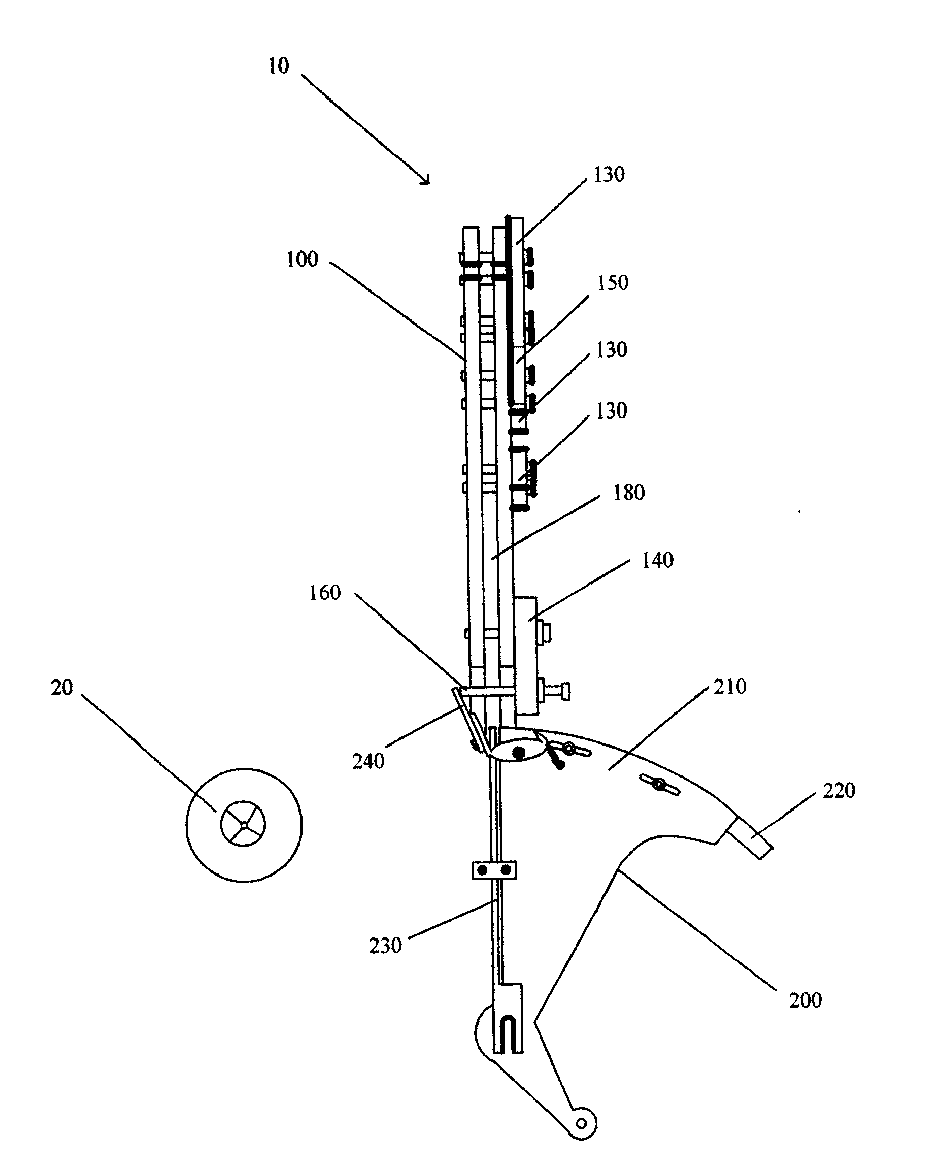
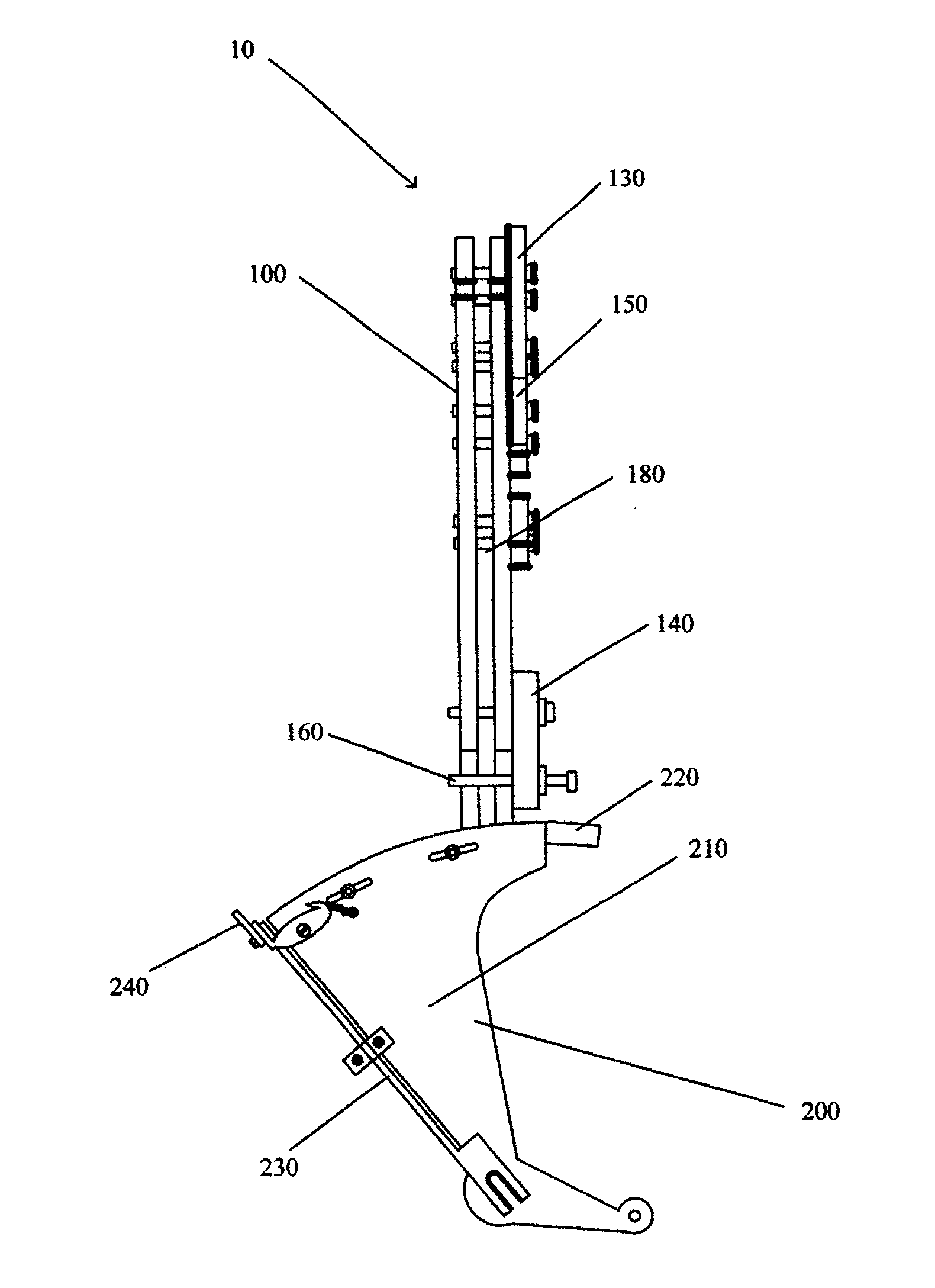
[0036] see figure 2 , image 3 and Figure 4 , The terminal conveying device 10 of the present invention includes a terminal sorting roller (not shown in the figure), a guiding mechanism 100 and a conveying mechanism 200 . The transmission mechanism 200 is slidably supported under the guide mechanism 100, and the transmission mechanism 200 can rotate around a rotation axis o (such as Figure 13 and Figure 14 shown) to rotate. The terminal 30 discharged from the terminal sorting roller slides along the guide mechanism 100 to the bottom end of the guide mechanism 100 and enters the transfer mechanism 200; then, the transfer mechanism 200 rotates around the rotation axis o to the position of a rotating clamp 20 and pushes the terminal 30 into The jig 20 is rotated for processing.

[0037] Please also refer to Figure 4 to Figure 7 , the guiding mechanism 100 has a first guiding rail 110 , a second guiding rail 120 , a plurality of adjusting plates 130 , a first fixing pla...


PUM


Abstract

A terminal conveyer is composed of the terminals sorting rollers, a guide unit consisting of the first and the second arc tracks to form a slide way and the retaining parts fixed to bottom, and a conveying mechanism consisting of rotary arms, moon hooks fixed to said rotary arm, rotary propulsion devices fixed to said rotary arm, and the press parts matched with said retaining parts for opening or closing it.

Description

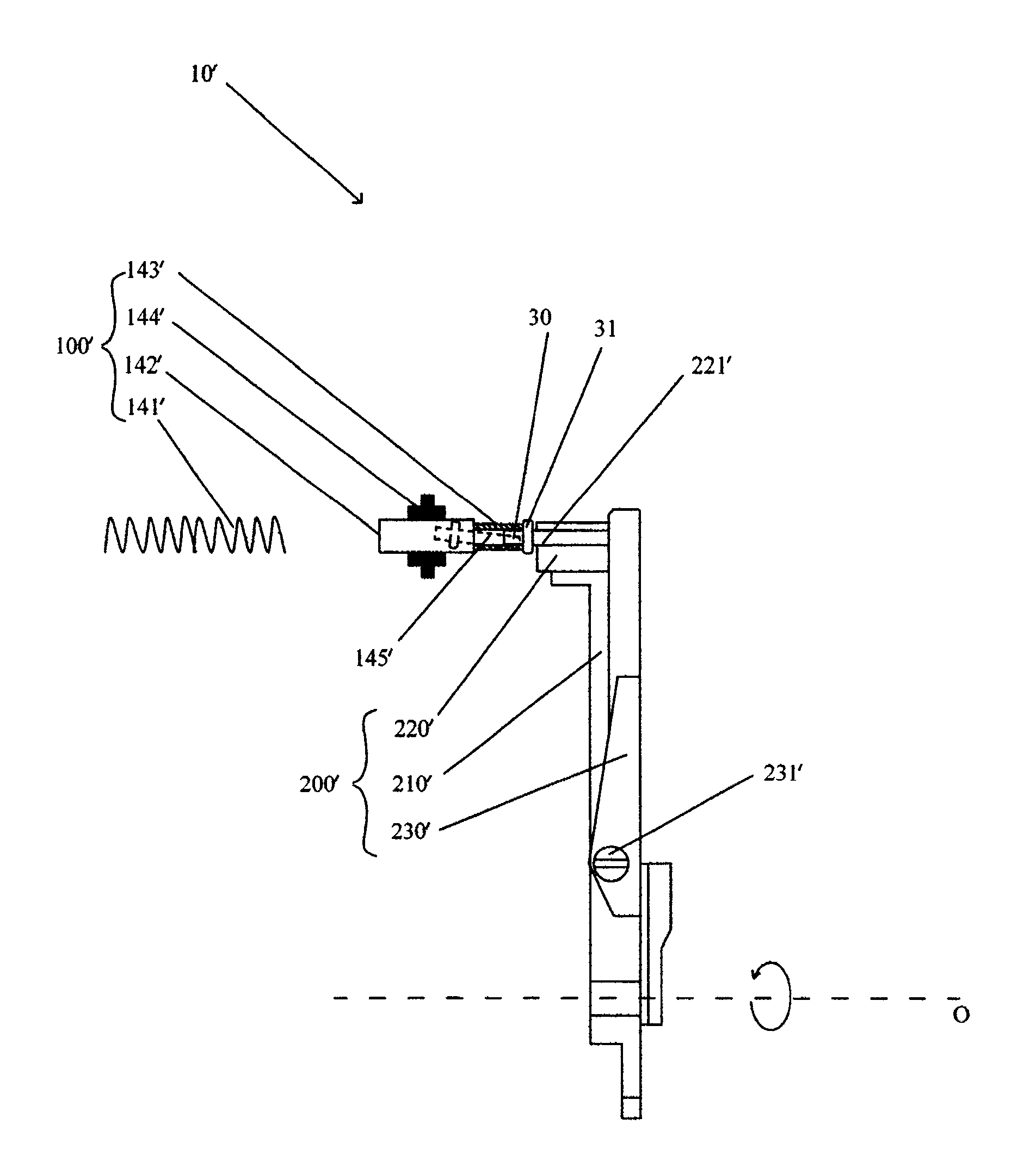
Technical field [0001] The invention relates to a terminal conveying device, in particular to a terminal conveying device for conveying a terminal to a rotary fixture for processing. Background technique [0002] like figure 1 As shown, the existing terminal conveying device 10' has a terminal sorting roller, a guiding mechanism 100' and a conveying mechanism 200'. When processing the terminal 30 with the shoulder shaft 31, the guide mechanism 100' sends the terminal 30 discharged from the terminal sorting roller to the transmission mechanism 200', and then the transmission mechanism 200' rotates around a rotation axis 0 to the position of the rotary fixture, and The terminal 30 is pushed into the rotary jig for processing. [0003] The guiding mechanism 100' includes a spring 141', a feeding tube 142', a joint 143' and a fixing frame 144'. The feeding tube 142' is fixed on the fixed frame 144'. The joint 143' is fixed on one end of the feeding pipe 142', and the joint 1...

Claims


Application Information

Patent Timeline
Patent Type & Authority Patents(China)
IPC IPC(8): B65G37/00B65G11/00B65G47/74
Inventor 李莉宏
Owner 李莉宏
Learn More