Information reception device, information transmission system, and information reception method

A technology of information receiving and information output, applied in transmission system, electromagnetic wave transmission system, free space transmission, etc., can solve problems such as uselessness

Inactive Publication Date: 2009-10-28
CASIO COMPUTER CO LTD
View PDF5 Cites 0 Cited by
  • Summary
  • Abstract
  • Description
  • Claims
  • Application Information

AI Technical Summary

Problems solved by technology

However, in the case where the point light source of the light emitting unit, especially the point light source located far away, has a relatively small and large visible size, since it can be sufficiently accommodated in one divided area, in this case, the Processing of other segmented regions that do not contain point lights is useless

Method used


Image

  • Information reception device, information transmission system, and information reception method
  • Information reception device, information transmission system, and information reception method
  • Information reception device, information transmission system, and information reception method

Examples


no. 1 Embodiment approach

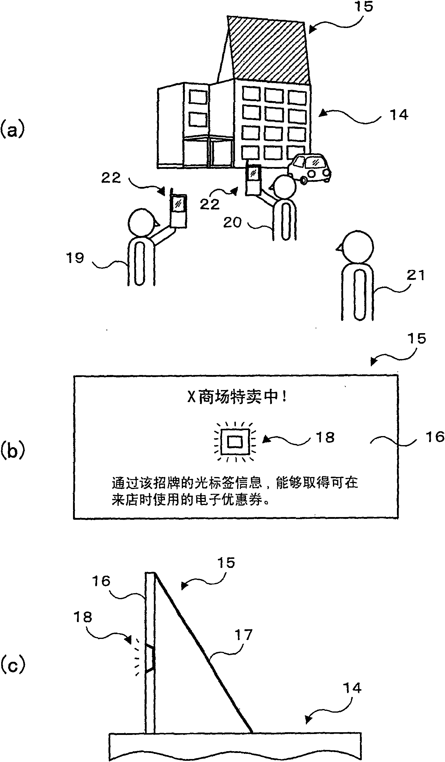
[0072] figure 1 It is a utilization state diagram of the information transmission system in 1st Embodiment. First, (a) will be described, and the advertisement display board 15 is installed on the roof of a building 14 such as a building. As shown in the front view in (b) and the side view in (c), the advertisement display board 15 has: arbitrarily drawn explanatory text columns ("X shopping mall is on sale!" in the figure), "through this signboard The signboard 16 that can obtain the electronic coupon ") that can be used when visiting the store, and the back fixed leg 17 that supports the signboard 16 from behind, and the explanatory text can be visually recognized from a distance.

[0073] An optical tag device 18 is attached to an arbitrary position (approximately central part in the illustrated example) of the signboard 16 . The light tag device 18 is a point light source that flickers in two pattern series. If you only look at the light tag device 18, you can only see ...

no. 2 Embodiment approach

[0176] In short, in the first embodiment above, the photodetector 61 is used as the light receiving mechanism for receiving the bright spot of the optical label device 18 , but it is not limited thereto. Any device may be used as long as it has a viewing angle corresponding to the size of the object to be provided with information (the optical tag device 18 ). For example, it may be an image sensor such as a CCD or a CMOS, or may have a structure in which a plurality of photodetectors are arranged on a plane.

[0177] Hereinafter, an embodiment using an image sensor such as a CCD or a CMOS (hereinafter referred to as a second embodiment) will be described.

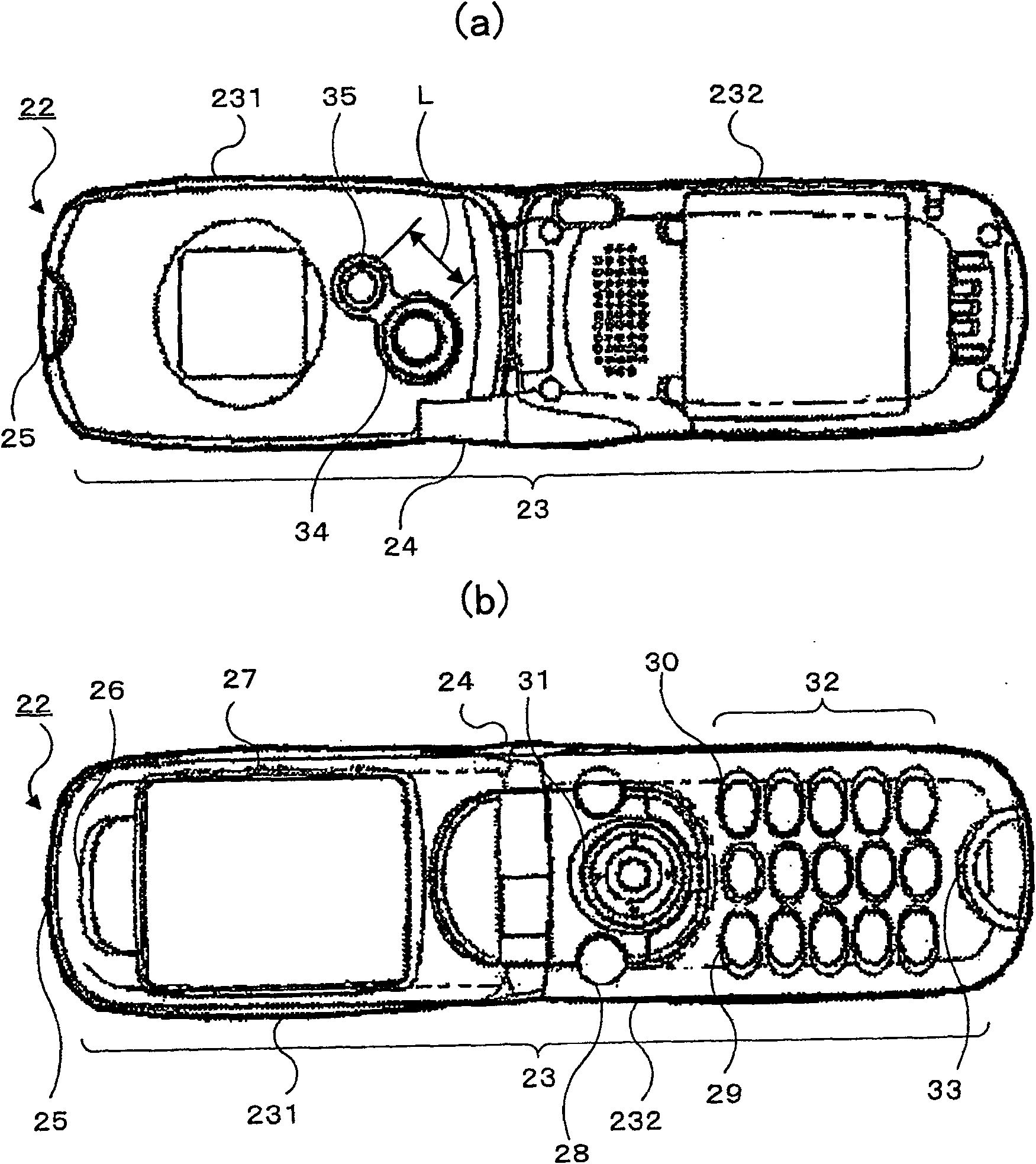
[0178] Figure 25 It is an internal block configuration diagram of the camera-equipped mobile phone 220 in the second embodiment. In this figure, the mobile phone with camera 220 is characterized in that an image sensor (hereinafter referred to as "communication image sensor 610" to distinguish it from image sensor 57 fo...


PUM


Abstract

By acquiring a region required for detection of a luminance modulation, it is possible to increase the speed of the information restoration process. Moreover, it is possible to facilitate the position adjustment of the luminance modulation region. An information reception device (22) includes: imaging means (34, 57); light reception means (35, 61) for photo-receiving arbitrary information subjected to luminance modulation; specification means (31, 53) for specifying a luminance modulation region contained in the imaging angle of view of the imaging means; restoration means (50, 53) for controlling the light reception means so as to photo-receive the luminance modulation region specified by the specification means and restoring arbitrary information from the luminance modulation content contained in the region; and reproduction means (47) for reproducing arbitrary information restored by the restoration means.

Description

technical field [0001] The present invention relates to an information receiving device, an information transmission system, and an information receiving method, which can be used, for example, for displaying landmarks such as buildings, displaying advertisements, displaying guides and crowded conditions of amusement facilities such as amusement parks, product descriptions in stores, museums, and exhibitions It can be used for various purposes such as explanations of exhibits at conferences. Background technique [0002] In the past, it has been used to display landmarks such as buildings, advertisement displays, guides for amusement facilities such as amusement parks, and display of crowded conditions, product descriptions in stores, and descriptions of exhibits in museums and exhibitions, written on paper, banners, signs, or display boards "Visual information" such as text or graphics on the "information reminder". [0003] However, in an environment with a large number o...

Claims


Application Information

Patent Timeline
Patent Type & Authority Patents(China)
IPC IPC(8): H04B10/10H04B10/105H04B10/22H04M1/21H04N5/225H04N5/232H04B10/11H04B10/116H04N5/91
Inventor 饭塚宣男永友正一
Owner CASIO COMPUTER CO LTD
Why Eureka
Try Eureka