Vehicular brake control apparatus and control method therefor

A technology of brake control and control method, which is applied in the direction of brakes, etc., which can solve the problems that the front wheels are alone, cannot realize sporty driving, and cannot obtain braking feeling, etc., and achieve the effect of good braking feeling

Inactive Publication Date: 2009-10-28
NISSIN KOGYO CO LTD
View PDF7 Cites 0 Cited by
  • Summary
  • Abstract
  • Description
  • Claims
  • Application Information

AI Technical Summary

Problems solved by technology

In this way, in conventional brake control devices, unlike conventional handle-type vehicles, the braking of the front and rear wheels cannot be performed independently according to the driver's will, so that a good braking feeling cannot be obtained.
Moreover, due to such interlocking braking, it is impossible to achieve a sporty driving that adapts to the driver's wishes, etc.

Method used


Image

  • Vehicular brake control apparatus and control method therefor
  • Vehicular brake control apparatus and control method therefor
  • Vehicular brake control apparatus and control method therefor

Examples


Embodiment Construction

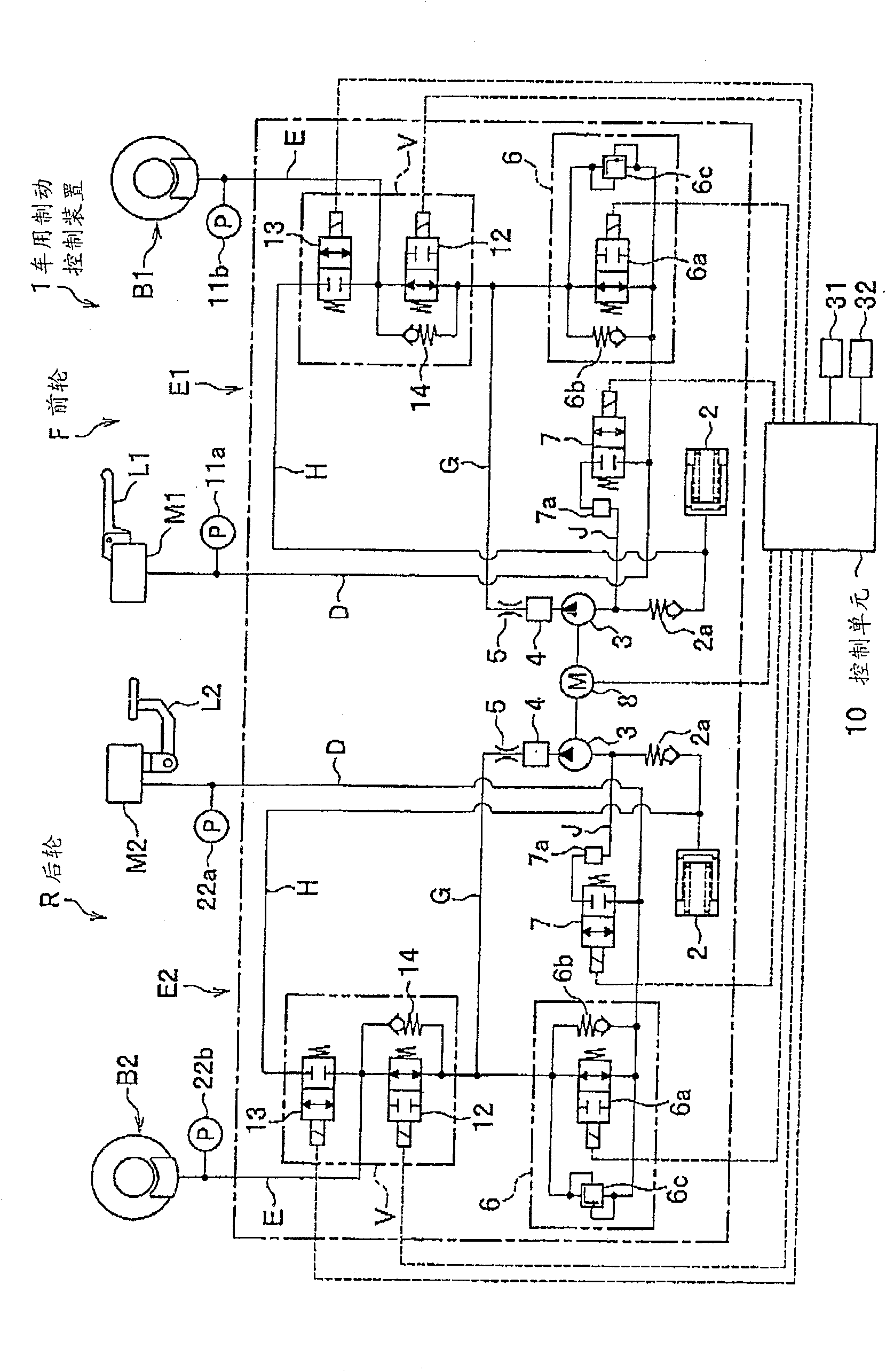
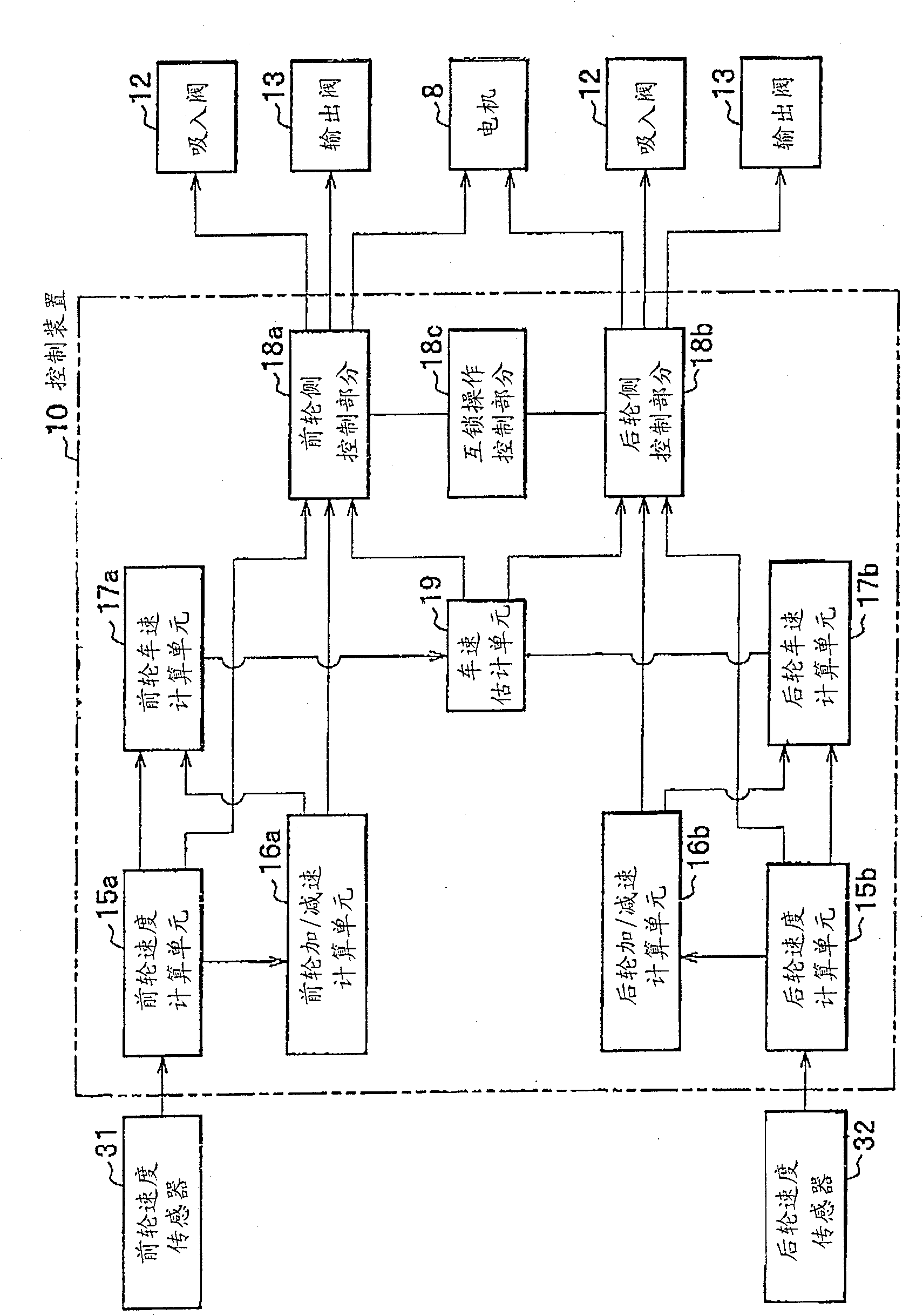
[0057] Hereinafter, the best mode for carrying out the present invention will be explained in detail based on the accompanying drawings. In the course of explanation, the same constituent elements are denoted by the same reference numerals, and the same descriptions are omitted. In the attached picture, figure 1 is a brake hydraulic circuit diagram of a vehicle brake control device according to an embodiment of the present invention, figure 2 It is a block diagram of the main structure of the control device.

[0058] The brake control device 1 is applicable to a handlebar type vehicle such as an auto tricycle, an auto bicycle, or an all-terrain vehicle (ATV), and is adapted to control the braking force applied to the front and rear wheels of the vehicle, not shown (via a brake hydraulic system). produced). Hereinafter, the brake control device applied to an automatic bicycle will be explained as an example. Such as figure 1 As shown, the brake control device 1 includes t...


PUM


Abstract

The control unit 10 controls the braking forces respectively acting on a pair of independently working brake operating elements L1, L2, so as to perform anti-lock braking control and prevent the wheels from possibly being locked. When the brake operating elements L1, L2 are activated, the control unit 10 applies the braking force to one of the wheel brakes B1, B2 of a braking system different from the braking system operated by the brake operating element . When one or both of the brake operating elements L1 and L2 work, and the wheel may be in a locked state, the control unit 10 performs anti-lock control on the braking system of the wheel that is about to be in the locked state, and at the same time, the brake Power is applied to another braking system than the one that is about to be locked.

Description

technical field [0001] The present invention relates to a vehicle brake control device and its control method, in particular, to a vehicle brake control device and its control method. On all-terrain vehicles (ATVs) on various terrains. Background technique [0002] Usually, the known brake control device for vehicle brakes the vehicle by electronically controlling the brake hydraulic pressure of the vehicle (for example, refer to Japanese publications whose publication numbers are JP-A-2000-127930 and JP-A-2000-264278 unexamined patent publication). [0003] The brake control devices for vehicles disclosed in these publications all have the following configurations, which can independently control the brakes of the front and rear wheels of the automatic bicycle, and can perform interlocking between the front wheels and the rear wheels. [0004] In these conventional vehicle brake control devices, the front and rear wheels are braked in an interlocked manner based on the op...

Claims


Application Information

Patent Timeline
Patent Type & Authority Patents(China)
IPC IPC(8): B60T8/1766
Inventor 小山彻
Owner NISSIN KOGYO CO LTD
Why Eureka
Try Eureka