
MgO evaporation material

A technology for evaporating materials and pellets, applied in vacuum evaporation plating, metal material coating process, sputtering plating, etc., can solve problems such as wrong addressing and insufficient strength, improve brightness and reduce manufacturing costs , The effect of reducing the number of address ICs

Inactive Publication Date: 2009-09-23
MITSUBISHI MATERIALS CORP
View PDF6 Cites 0 Cited by
  • Summary
  • Abstract
  • Description
  • Claims
  • Application Information

AI Technical Summary

Problems solved by technology

Since this confusion phenomenon does not turn on all the selected cells in one row or one column, but occurs scatteredly, the cause of the black noise is that the address discharge does not occur, or even if it occurs, it is other Insufficient strength error addressing

Method used


Image

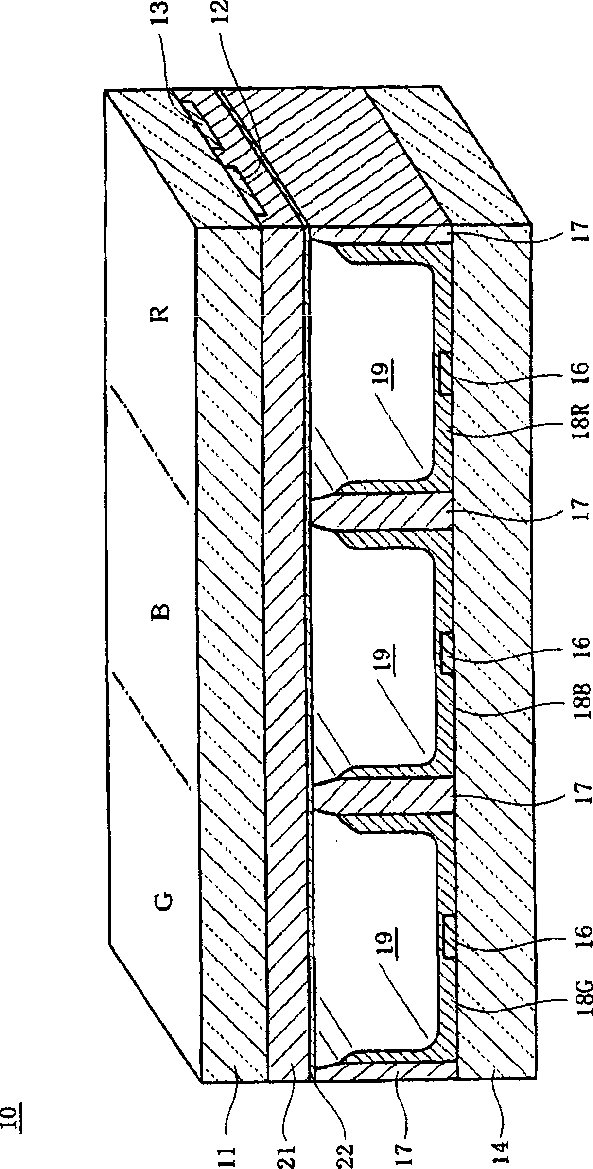
  • MgO evaporation material
  • MgO evaporation material

Examples


Embodiment 1

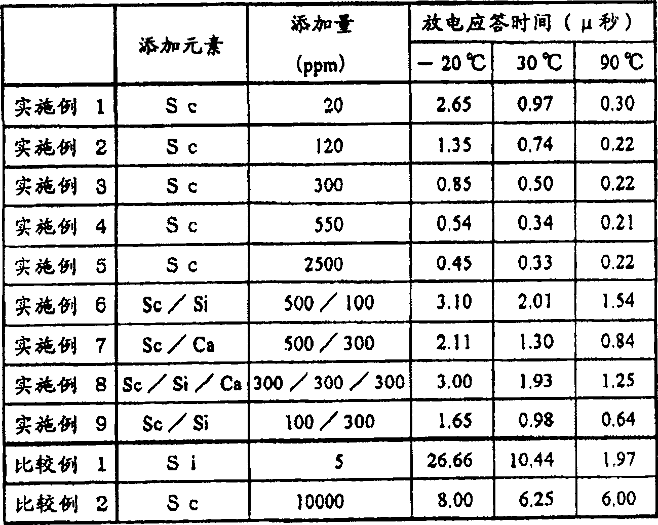
[0070] As a MgO vapor deposition material, polycrystalline MgO pellets with a purity of 99.95% of MgO, a relative density of 98%, and a concentration of Sc contained in MgO of 20 ppm were prepared. The diameter and thickness of the MgO vapor deposition material are 5 mm and 1.6 mm, respectively. In addition, an ITO electrode and a silver electrode were formed on the surface area to form electrodes, and in order to cover the electrodes, a glass substrate on which a dielectric glass layer was formed was prepared.

[0071] On the upper surface of the dielectric glass layer formed on the glass substrate, the above-mentioned MgO vapor deposition material was used to form a film thickness of (800nm), MgO film with (111) plane orientation. The film forming condition is that the final vacuum degree is 1.0×10 -4 Pa, oxygen partial pressure is 1.0×10 -2 Pa, substrate temperature is 200℃, film forming speed is / Sec (2nm / sec).

Embodiment 2

[0073] The MgO film was formed by the same method as in Example 1, except that a MgO vapor deposition material having a Sc concentration of 120 ppm contained in the MgO pellets was used.

Embodiment 3

[0075] The MgO film was formed by the same method as in Example 1, except that a MgO vapor deposition material with a Sc concentration of 300 ppm contained in the MgO pellets was used.


PUM

PropertyMeasurementUnit
thicknessaaaaaaaaaa

Abstract

A MgO evaporation material for forming a protective film of a plasma display panel, comprising MgO pellets with a MgO purity of more than 98% and a relative density of more than 90%. The pellets contained only Sc elements as rare earth elements. The concentration of the Sc element is 5 to 5000 ppm, preferably 10 to 3000 ppm, more preferably 20 to 2000 ppm.

Description

Technical field [0001] The present invention relates to a MgO vapor deposition material, which is a material for forming a MgO film used as a protective film material of an AC type plasma display panel. In more detail, it relates to a MgO vapor deposition material, which forms a MgO film with good responsiveness in a wide temperature range, and a plasma display panel material using the MgO film. [0002] This application is based on Japanese Patent Application No. 2004-206623 filed with the Japanese Patent Office on July 14, 2004, Japanese Patent Application No. 2004-272720 filed with the Japanese Patent Office on September 21, 2004, and Japanese Patent Application No. 2004-272720 on December 28, 2004. The priority of Japanese Patent Application No. 2004-379090 filed by the Patent Office and Japanese Patent Application No. 2005-117718 filed by the Japanese Patent Office on April 15, 2005 are cited here. Background technique [0003] In recent years, the research and development a...

Claims


Application Information

Patent Timeline
Patent Type & Authority Patents(China)
IPC IPC(8): C23C14/24H01J11/02C04B35/04H01J17/49
Inventor 樱井英章黛良享平田宽树
Owner MITSUBISHI MATERIALS CORP
Learn More