Light modulator

A technology for a dimming device and a mounting member, which is applied to lighting devices, light sources, and components of lighting devices, etc., can solve the problems of the bidirectional three-terminal thyristor Q being unable to maintain the conduction state and non-conducting, and achieve heat dissipation. Improves, suppresses temperature rise, and reduces assembly area

Inactive Publication Date: 2009-09-09
MATSUSHITA ELECTRIC WORKS LTD
View PDF5 Cites 0 Cited by
  • Summary
  • Abstract
  • Description
  • Claims
  • Application Information

AI Technical Summary

Problems solved by technology

Then, when approaching the zero-crossing point of the AC power supply Vs, the bidirectional three-terminal thyristor Q cannot maintain the conduction state and becomes non-conduction

Method used


Image

  • Light modulator
  • Light modulator
  • Light modulator

Examples


Embodiment 1

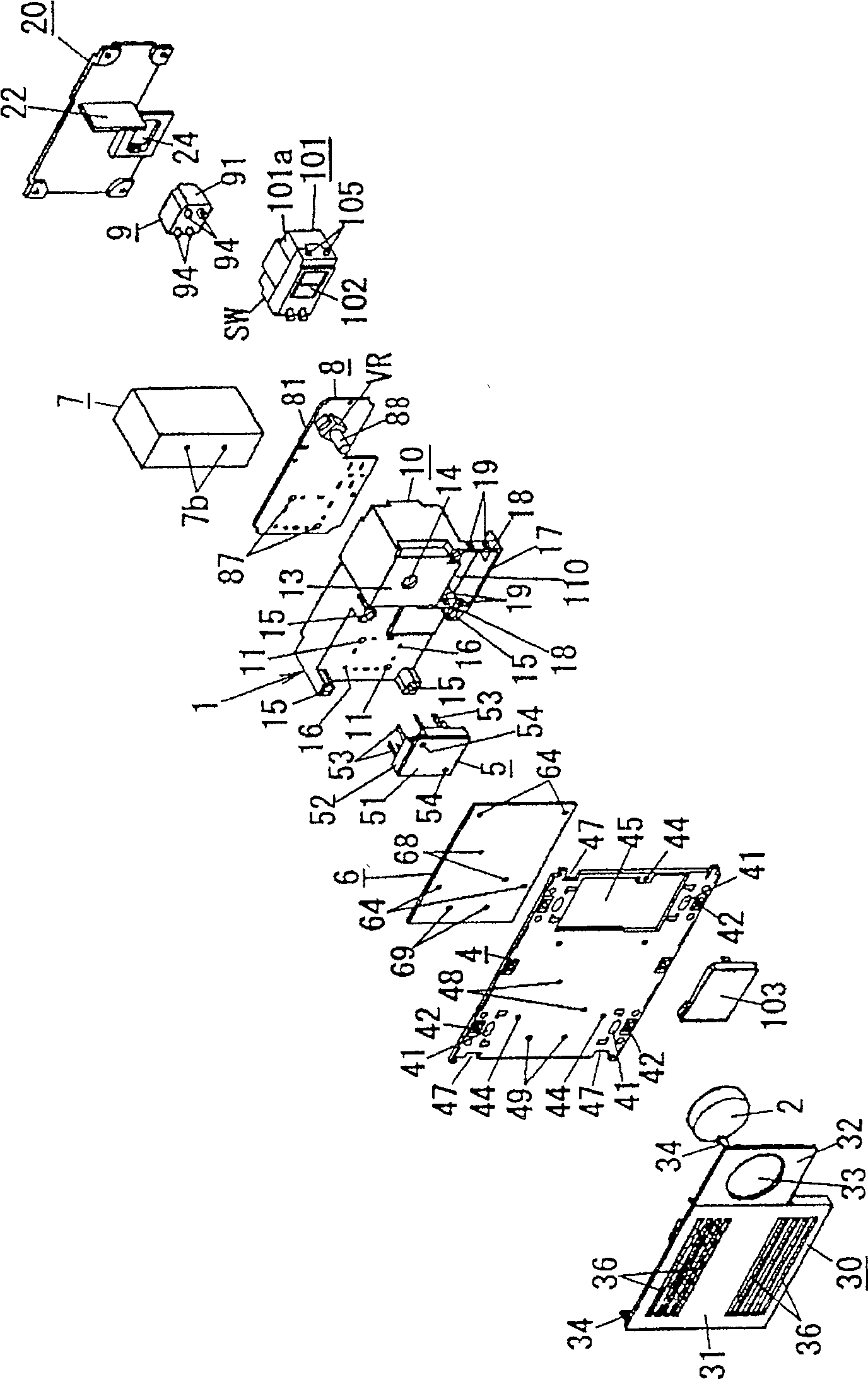
[0094] Below, refer to Figure 1 to Figure 10 The dimming device of this embodiment will be described. In addition, due to the circuit structure of the dimming device of this embodiment and Figure 13 The circuit structures shown are the same, and illustration and description are omitted.

[0095] The dimming device of this embodiment is constructed by embedding part of it in a construction surface such as a wall, and is used to control the dimming of lighting loads La such as incandescent lamps. The metal mounting plate 4 corresponding to the triple use mounting frame used in the type wiring appliance. That is, the mounting plate 4 is formed of a metal material such as aluminum, and the overall shape is formed so that three of them can be installed in three rows in a row. Corresponds to the installation frame for triple use of the unit size of the installation of up to 3 units of wiring equipment (the external dimension is formed to be equal to the installation frame for t...

Embodiment 2

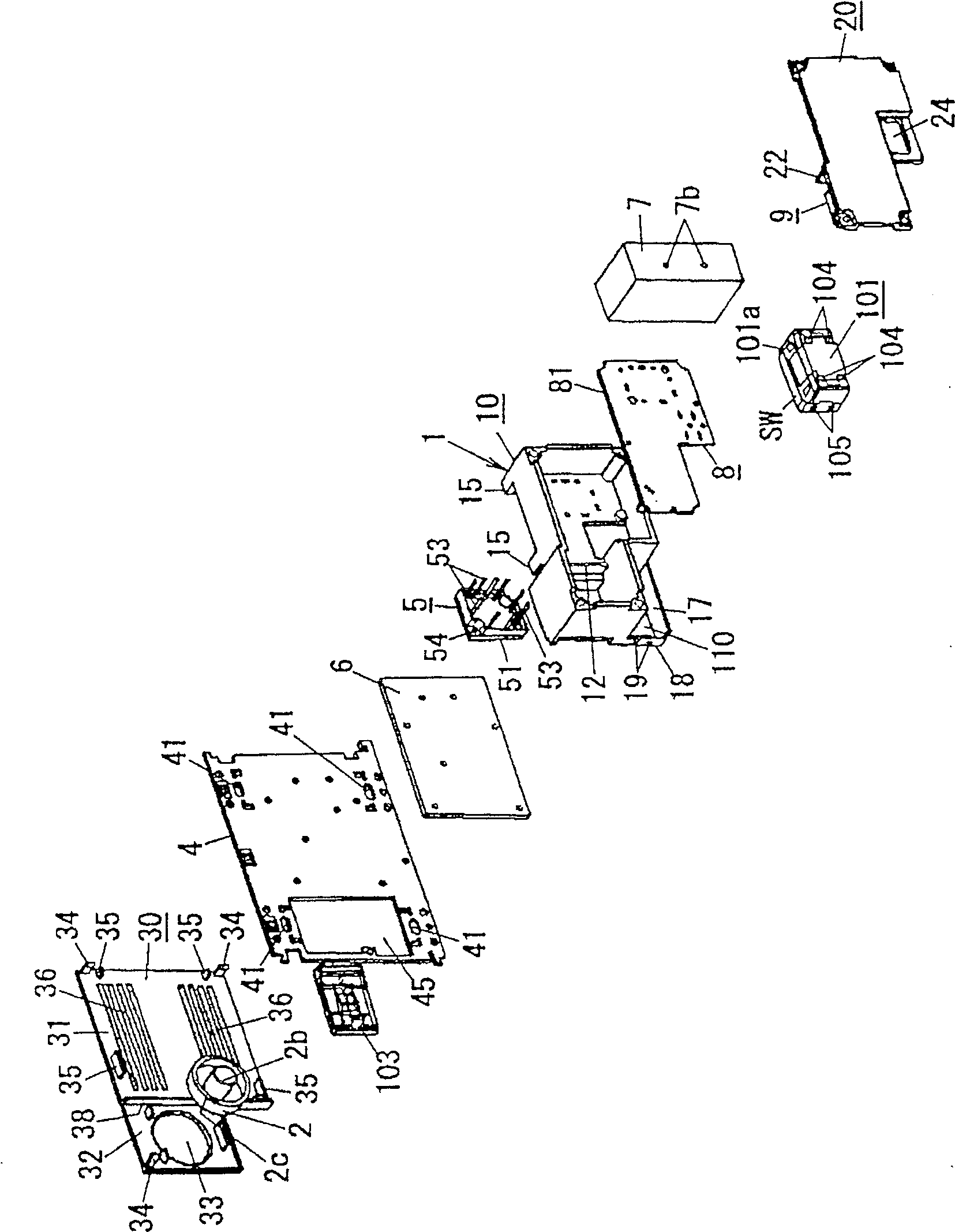
[0119] The basic structure of the dimming device of this embodiment is roughly the same as that of Embodiment 1. It is characterized in that the material used in Embodiment 1 is the heat dissipation plate 6 and heat dissipation block 7 of the thermal bonding member and the installation plate 4 of the installation member. The same metal material (such as aluminum), such as Figure 11 As shown, the heat dissipation plate 6, the installation plate 4 and the heat dissipation block 7 are integrally formed by metal mold casting (aluminum mold casting), which is the same as the case where the heat dissipation plate 6, the installation plate 4 and the heat dissipation block 7 are separately formed as in Embodiment 1. Ratio, the assembly is improved, and the thermal conductivity is improved, and the heat dissipation efficiency is improved. Since other structures are the same as those in Embodiment 1, explanations are omitted. In this embodiment, the heat sink plate 6, the mounting pla...


PUM


Abstract

The invention provides a dimming device to adjust lighting load of light output with high capacity while preventing occurrence of high frequency noise and also achieve high heat dissipation characteristic and miniaturization. The dimming device includes a triac and a serial circuit having a pair of IGBTs connected among main terminals of the triac and also includes a power module 5 and a control circuit. The triac and the pair of IGBTs are provided on the aluminum substrate of the power module 5 by bare chip packaging, respectively. The control circuit turns on the triac with a phase angle corresponding to dimming level set by variable resistance VR at first and controls the impedance of one of the pair of IGBTs to smoothly increase loading voltage for applying on the lighting load. The power module 5 is thermally combined with a fitting plate 4 as fitting member material provided on the application surface of the power module 5 while a heat dissipating plate 6 is provided in between.

Description

technical field [0001] The invention relates to a dimming device for dimming an illumination load by controlling the phase of an AC power supply. Background technique [0002] A dimming device has been proposed in the past (for example, refer to Patent Document 1), which assembles a bidirectional three-terminal thyristor (Triac), a variable resistor, and Such printed circuit boards are stored in the container, and by controlling the phase of the bidirectional three-terminal thyristor, the power supply to the lighting load is controlled, so that the light output of the lighting load can be adjusted. This kind of dimming device is provided with an operating part on the front of the container to set the dimming level of the lighting load by adjusting the resistance value of the variable resistor. In addition, it is also proposed to provide a heat sink for dissipating the heat generated in the bidirectional three-terminal thyristor in the dimming device using the bidirectional ...

Claims


Application Information

Patent Timeline
Patent Type & Authority Patents(China)
IPC IPC(8): H05B37/02H05B39/04H05B41/36F21V23/00F21V29/00F21Y101/00
CPCY02B20/14Y02B20/146Y02B20/202Y02B20/00
Inventor 向井达哉福岛政治北村常弘村田之广冈田健治
Owner MATSUSHITA ELECTRIC WORKS LTD
Why Eureka
Try Eureka