
Car engine camshaft bearing cap

A technology for automobile engines and camshafts, which is applied to engine components, machines/engines, cylinder heads, etc., can solve the problems of complicated processing technology of oil holes in cylinder heads, increased engine volume and large frame volume, etc., and can reduce the machining process. Difficulty, compact structure, the effect of simplifying the process

Inactive Publication Date: 2009-08-26
CHERY AUTOMOBILE CO LTD
View PDF6 Cites 5 Cited by
  • Summary
  • Abstract
  • Description
  • Claims
  • Application Information

AI Technical Summary

Problems solved by technology

[0002] Now domestic automobile engine camshafts are mostly fixed on the cylinder head through an integral frame installed above the cylinder head and fixed by several bolts. The frame is cast with camshaft bearing holes corresponding to the cylinder head. Each shaft diameter The oil supply must be drilled on the cylinder head. The frame is bulky, which increases the volume space of the engine, and the oil hole processing process on the cylinder head is complicated.

Method used


Image

  • Car engine camshaft bearing cap
  • Car engine camshaft bearing cap
  • Car engine camshaft bearing cap

Examples


Embodiment Construction

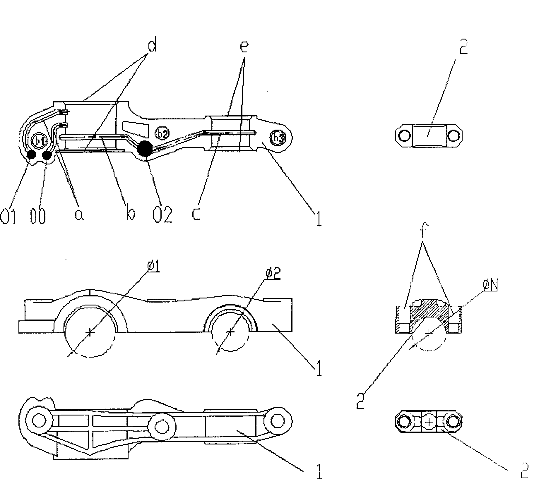
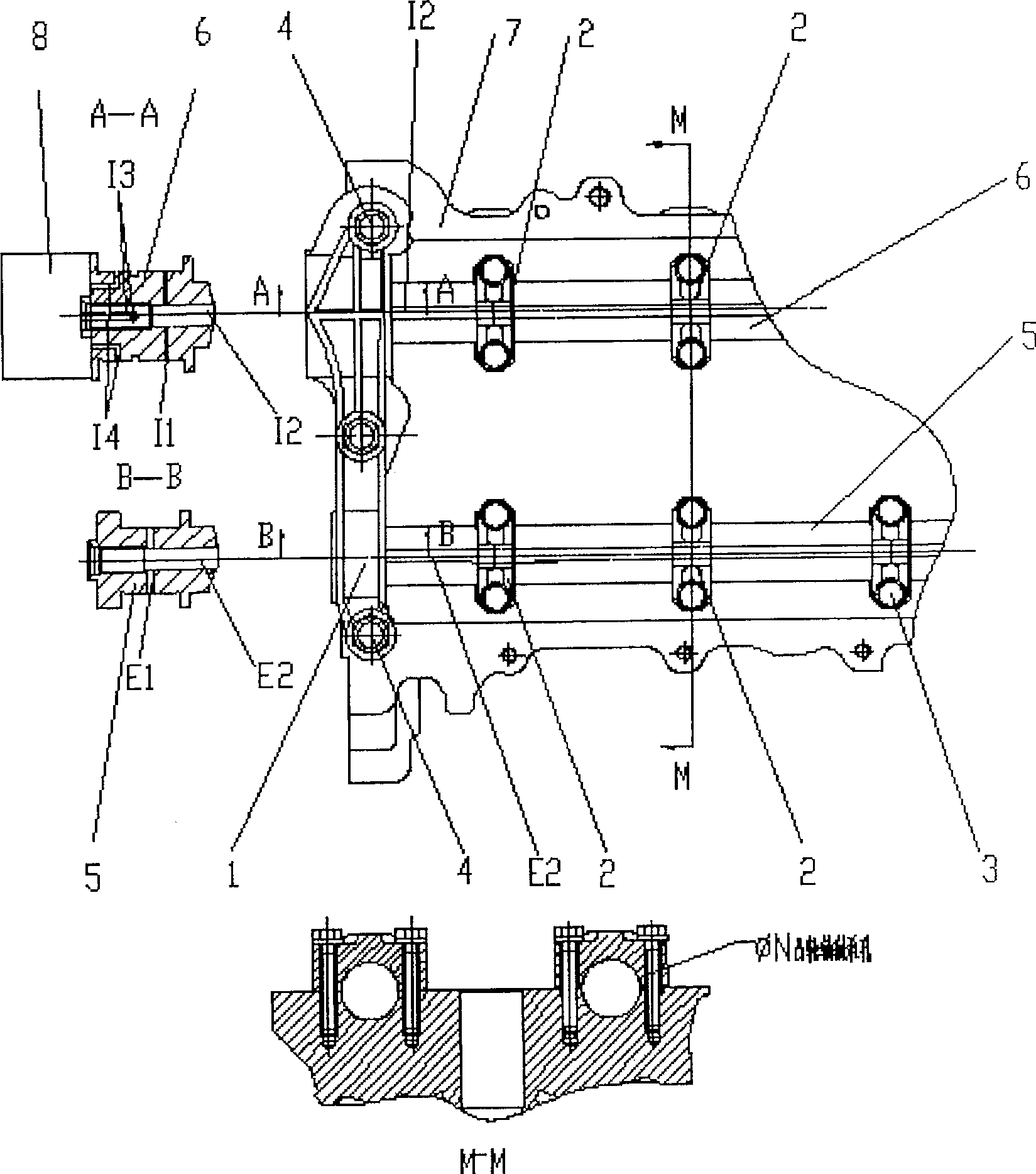
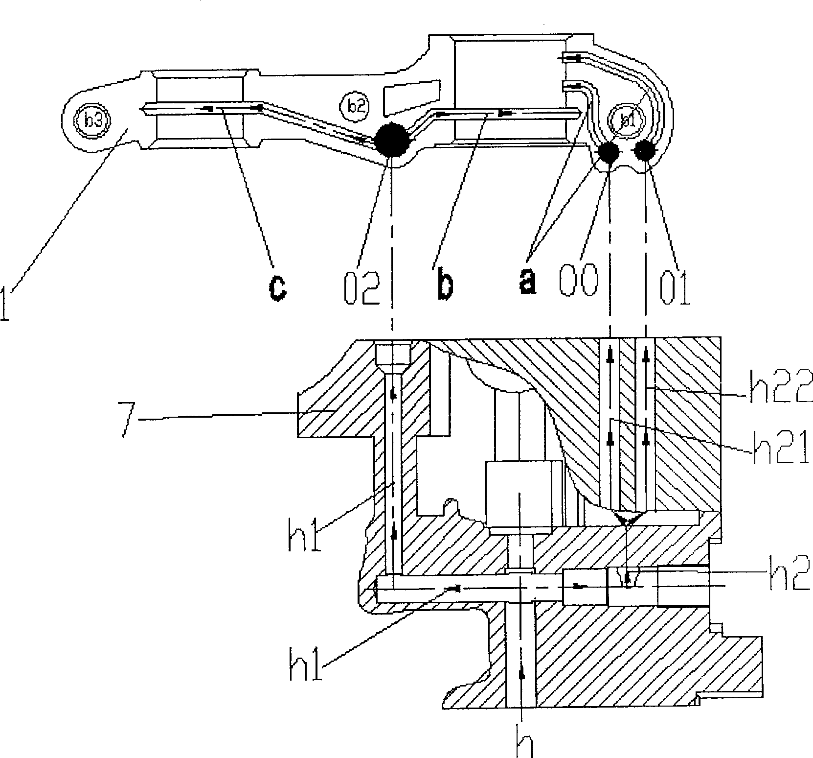
[0018] Below in conjunction with accompanying drawing, the automobile engine camshaft bearing cap of the present invention is described in further detail.

[0019] refer to figure 1 , 3 , discloses the automobile engine camshaft bearing cap of the present invention, comprises the first camshaft bearing cap 1, the second to N camshaft bearing caps 2, that is, there are multiple bearing caps with the same structure as the second camshaft bearing cap. First camshaft bearing cap 1 and multiple second camshaft bearing caps figure 2 Installed on the engine cylinder head 7, constitute the shaft diameter holes φ1, φ2 and several φN of the camshafts 5, 6 together. The first camshaft bearing cap 1 is positioned by combining the two positioning sleeves 4 installed on the cylinder head 7 with the cylinder head, and the second to N camshaft bearing caps 2 are positioned by combining the positioning bolts 3 with the cylinder head 7 , to ensure the coaxiality of the camshaft hole. The e...


PUM


Abstract

The invention provides a cam shaft bearing cover of auto engines, comprising a first cam shaft bearing cover and a plurality of second cam shaft bearing covers. The first cam shaft bearing cover and the second cam shaft bearing covers are positioned on an engine cylinder cover, thus forming a shaft diameter hole of a cam shaft. A petrol tunnel communicated with an intake VVT phaser and an intake cam shaft and an exhaust cam shaft is cast on a matching surface of the first cam shaft bearing cover and the cylinder cover. Grease from a cylinder body enters from the petrol hole of the cylinder cover and then is divided into two ways, one flows into the intake cam shaft and the exhaust cam shaft along the petrol tunnel and then flows directly to shaft diameter parts of a plurality of cam shaft bearing covers to grease the cam shaft bearing cover, while the other way flows into the intake VVT phaser along the petrol tunnel. The cam shaft bearing cover of auto engines of the invention has simple cast technique, compact structure, and dramatically reduces occupying space of the cylinder cover on the whole engine and the weight on the whole engine weight.

Description

technical field [0001] This invention relates to camshaft bearing caps for high speed automotive engines. Background technique [0002] Now domestic automobile engine camshafts are mostly fixed on the cylinder head through an integral frame installed above the cylinder head and fixed by several bolts. The frame is cast with camshaft bearing holes corresponding to the cylinder head. Each shaft diameter The oil supply must drill oil holes on the cylinder head, the frame is bulky, which increases the volume space of the engine, and the processing technology of the oil holes on the cylinder head is complicated. Contents of the invention [0003] The purpose of the present invention is to provide a camshaft bearing cover structure of an automobile engine, so that each shaft diameter of the camshaft corresponds to a bearing cover, and the oil passage leading to the camshaft and the intake VVT ​​is cast on the first camshaft bearing cover. The process is simple and the structure...

Claims


Application Information

Patent Timeline
Patent Type & Authority Patents(China)
IPC IPC(8): F02F1/38F01L1/047F01M9/10
CPCF01L2001/0476
Inventor 慕金华
Owner CHERY AUTOMOBILE CO LTD
Learn More