
Cotton roll equal length gradually pressurizing structure and control device thereof

A technology of gradually increasing pressure and lap, applied in the field of blowing and rolling machines, can solve the problems of poor effect, unreasonable, and the draft length of cotton lap does not meet the national standard, etc., and it is more scientific to achieve reasonable pressure on the cotton layer. , the effect of accurate value accuracy

Active Publication Date: 2009-08-26
SAURER CHANGZHOU TEXTILE MACHINERY CO LTD
View PDF7 Cites 0 Cited by
  • Summary
  • Abstract
  • Description
  • Claims
  • Application Information

AI Technical Summary

Problems solved by technology

[0003] Aiming at the deficiencies of the existing technology, people are exploring other improvement schemes. Now a new type of blowing and lapping machine has appeared in the market. It uses an electromagnetic damper to control the pressure of the lap pressing hook. The electromagnetic damper is installed on the On the pressurized transmission shaft, the electromagnetic damper is a kind of electromagnetic brake. Its braking torque is proportional to the input current. The formula of the braking torque is: M=I*K, K is a constant, and the input current varies with the The radius change of the cotton lap is determined by the displacement sensor. Since the input current of the electromagnetic damper is only related to the radius increase of the cotton lap, when the radius of the cotton lap increases by a certain thickness, the rolled The length of the cotton layer is different, so it is unreasonable to choose the radius of the cotton lap as the basic parameter for changing the input current of the electromagnetic damper. Practice has proved that the effect of using such a control mode to control the lap quality of the cotton lap is not good. The draft length of the lap does not meet the national standard

Method used


Image

  • Cotton roll equal length gradually pressurizing structure and control device thereof
  • Cotton roll equal length gradually pressurizing structure and control device thereof
  • Cotton roll equal length gradually pressurizing structure and control device thereof

Examples


Embodiment Construction

[0012] The specific embodiment of the present invention is described in further detail below in conjunction with accompanying drawing:

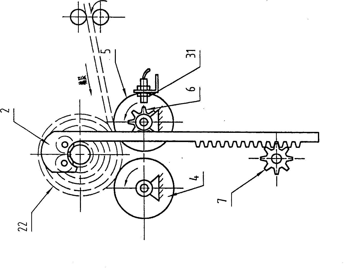
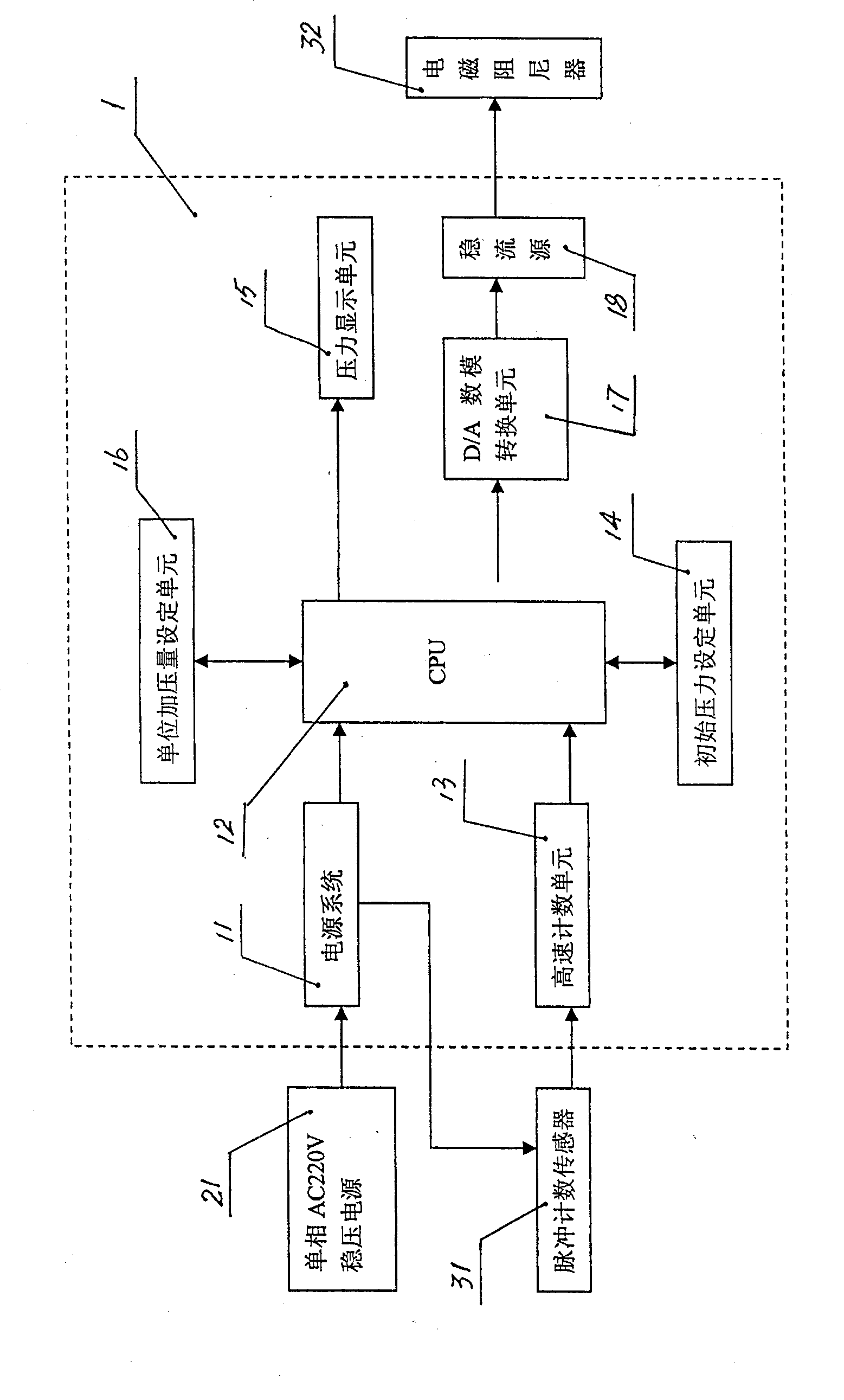
[0013] Depend on figure 1 , figure 2 , image 3 It can be seen that the equal-length and gradually increasing pressure mechanism of the lap according to the present invention is composed of the lap 22, the lap press hook 2, the lap roller 3, the front lap roller 4, the rear lap roller 5, the detection disc 6, and the gear 7 , a pressurized transmission shaft 8, a pulley 9, a motor 10, a pulse counting sensor 31, an electromagnetic damper 32, a control device, etc., the two gears 7 and the electromagnetic damper 30 are fixedly installed on the pressurized transmission shaft 8, and the gear 7 It meshes with the rack on the lap press hook 2, the front lap roller 4 and the rear lap roller 5 are in contact with the lap 22, and the detection disc 6 is installed on the rear lap roller 5 or on the front lap roller 4 , eight signal collection poin...


PUM


Abstract

A lap equal-length gradually increasing pressure mechanism and its control device, including a detection disc, an electromagnetic damper, a pulse counting sensor, and a control device, the detection disc is installed on the front lap roller or the rear lap roller, the electromagnetic damper, pulse counting The counting sensors are electrically connected with the control device. The pulse counting sensor collects the cotton layer rolling signal through the detection disc, and inputs it into the digital / electrical signal conversion processor to generate a current signal. The current signal is amplified by the current amplifier and then sent to the electromagnetic damper. The electromagnetic damper generates a corresponding damping torque; since the present invention is based on the mathematical model of increasing pressure per unit winding length, every time the detection disc rotates through a certain angle, the counting sensor can promptly notify the control device to increase the input of the electromagnetic damper Electric current, the electromagnetic damper generates corresponding damping torque, which makes the cotton layer pressurized more accurately and more reasonably, and its value accuracy is more accurate than that of the prior art.

Description

Technical field: [0001] The invention relates to a blowing and rolling machine, in particular to a gradual increasing pressure mechanism of the machine. Background technique: [0002] Blowing lap machine is one of the key equipment in the spinning process. Whether the layers of the lap are consistent in tightness and whether the elongation of the lap meets the standard is one of the main indicators to measure the quality of the lap machine. Existing cleaning machine is realized by adopting heavy hammer type gradually increasing pressure mechanism. On the A076 series lap forming machine, the gradual increasing and pressing mechanism is a purely mechanical structure. When forming a lap, the cotton lap continues to increase, which drives the lap pressing hook to rise, and the rack on the lap pressing hook and the gear with the brake disc Mesh with each other, through the transmission of gears, racks, and lap pressure hooks. When the cotton lap increases, the lap pressure hook ...

Claims


Application Information

Patent Timeline
Patent Type & Authority Patents(China)
IPC IPC(8): D01G27/02
Inventor 潘雪平
Owner SAURER CHANGZHOU TEXTILE MACHINERY CO LTD
Learn More