Compressed air engine electrically driven whole-variable valve actuating system

An electric drive, compressed air technology, applied in the direction of engine components, variable capacity engines, machines/engines, etc., can solve the problems of large liquid inertia force, high machining precision, and complex structure of electro-hydraulic variable valve system, and achieve structural Simple, achieve recycling, low energy consumption

Inactive Publication Date: 2009-07-29
ZHEJIANG UNIV
View PDF10 Cites 0 Cited by
  • Summary
  • Abstract
  • Description
  • Claims
  • Application Information

AI Technical Summary

Problems solved by technology

However, the electro-hydraulic variable valve system has the disadvantages of obvious changes due to the influence of temperature, large inertial force of the liquid, and large energy consumption.
The working principle of the electric drive method is roughly the same as that of the electro-hydraulic drive method, except that the working medium is replaced by compressed air. Compared with the electro-hydraulic drive, the compressed air responds faster than the liquid, and the quality is lighter. The viscosity of the air is affected by the temperature. Less impact, but higher energy consumption due to compressed air systems being less efficient than hydraulic systems
U.S. Patent No. [473948] proposes an electric valve driving method. The driving device adopts a reciprocating slide valve structure, which is complex in structure and requires high machining accuracy.

Method used


Image

  • Compressed air engine electrically driven whole-variable valve actuating system

Examples


Embodiment Construction

[0015] The present invention will be described in detail below in conjunction with the accompanying drawings.

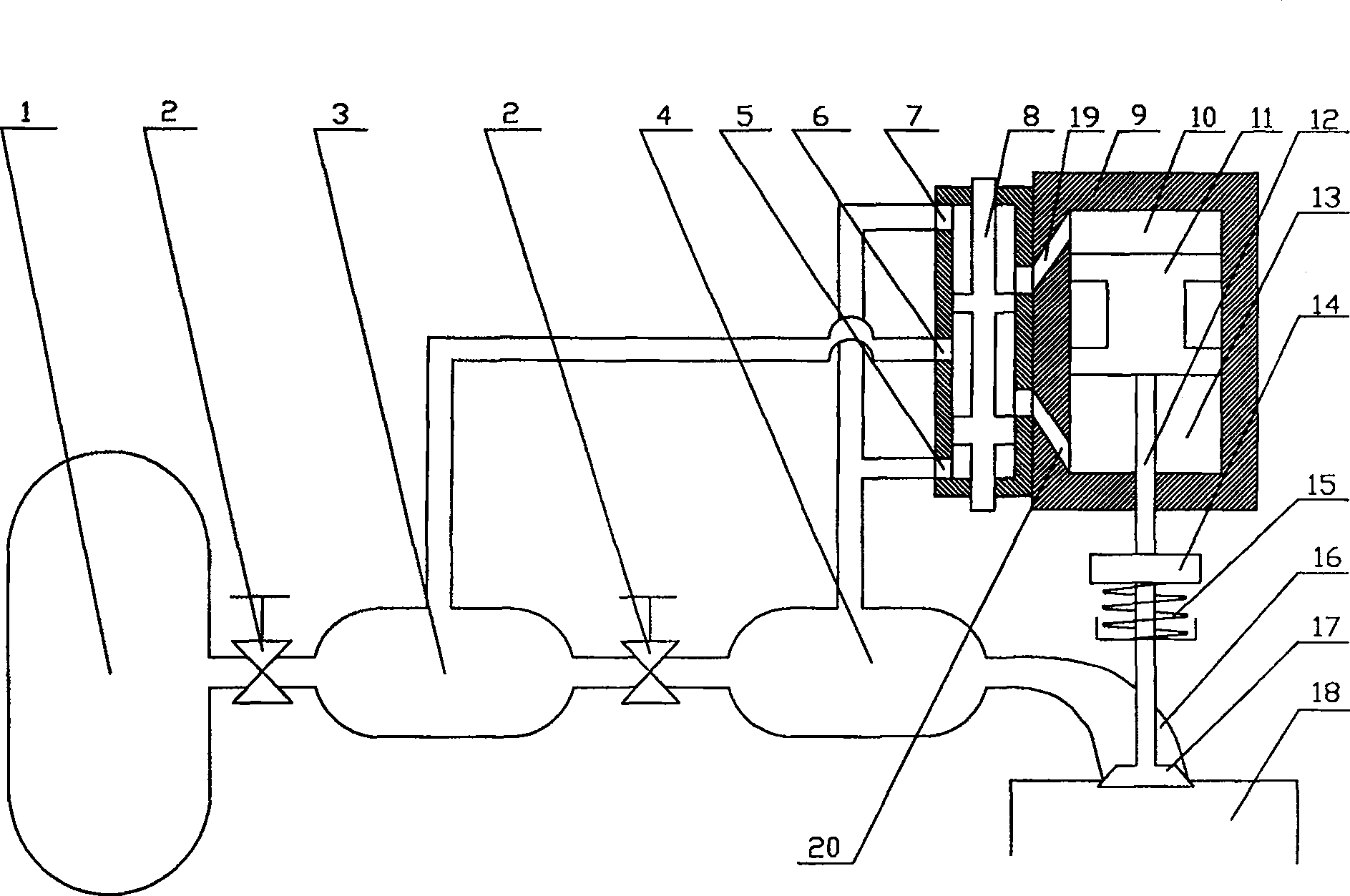
[0016] In this embodiment, the compressed air engine electrically drives the fully variable valve drive system such as figure 1 As shown, it includes a high-pressure gas storage tank 1, a surge tank 4 (secondary decompression gas tank) and a valve 17 located on the cylinder 18. The surge tank 4 is connected to the cylinder 18 through the intake manifold 16, and the valve 17 is sequentially connected. Connected are the valve spring 15, the coupling 14, the piston rod 12 and the piston 11, so the opening and closing movement of the valve 17 is realized by the reciprocating movement of the piston 11.

[0017] The piston 11 is located in the control cylinder 9, and divides the inner chamber of the control cylinder 9 into an upper working chamber 10 and a lower working chamber 13, and the upper working chamber 10 and the lower working chamber 13 pass through the upper wor...


PUM


Abstract

The invention relates to a compressed air engine device, aiming at providing a fully variable valve driving system of the compressed air engine. The system mainly includes valve springs, couplings, piston rods and pistons connected in sequence with the valves, and the pistons are located in the control cylinder. Based on the different action termination positions of the electromagnetic reversing valve, there are two communication states between the gas channel connected to the electromagnetic reversing valve and the exhaust port. The valve opening duration is controlled by controlling the pulse length of the electromagnetic reversing valve. The present invention has the advantages of realizing the decoupling of the valve motion of the pneumatic engine and the crankshaft speed, adjusting the optimal gas distribution phase according to the working conditions of the pneumatic engine; realizing the braking energy recovery of the vehicle in the working mode of the compressor, and during the recovery process The medium braking strength can be easily adjusted; the energy wasted in the decompression process is used to drive the valve to realize the recovery and utilization of decompression energy, and the energy consumption is very small; the structure is simple and easy to implement.

Description

technical field [0001] The invention relates to a compressed air engine device, more specifically, the invention relates to a fully variable valve drive system of the compressed air engine. Background technique [0002] The continuous soaring of fuel prices and the increasing environmental pollution caused by fuel vehicles have made countries all over the world step up the research and development of new energy vehicles. The pneumatic engine uses compressed air and liquid nitrogen as the working medium, does not need to consume oil during the work process, and can achieve zero emissions, which is a development direction. The main power source of the compressed air engine comes from the compressed air entering the cylinder, and its load is mainly realized by adjusting the amount of air entering the cylinder. The control of the intake air volume can be completed by adjusting the intake pressure and the intake time. However, the throttle control method is used to adjust the i...

Claims


Application Information

Patent Timeline
Patent Type & Authority Patents(China)
IPC IPC(8): F01L9/02F01L13/00F01B3/10F01L9/10F01L9/40
Inventor 陈平录俞小莉沈瑜铭刘林聂相虹胡军强
Owner ZHEJIANG UNIV
Why Eureka
Try Eureka