Cutting unit for sewing machine

A sewing machine and cutter technology, which is applied to sewing machine components, sewing equipment, textiles and papermaking, etc., can solve the problem that the fixing structure of the lower cutter cannot be fixed reliably, the resistance and stability of the lower cutter are poor, and it is difficult to meet the quality requirements. and other problems, to achieve the effect of increased smoothness, high structural stability and extended service life

Active Publication Date: 2009-07-15
曾贤长
View PDF5 Cites 0 Cited by
  • Summary
  • Abstract
  • Description
  • Claims
  • Application Information

AI Technical Summary

Problems solved by technology

[0003] 1. Insufficient stability of the upper cutting knife: Since the upper cutting knife is fixed on a knife seat, and the knife seat can be translated in the transmission mechanism to adjust the position of the upper cutting knife, so the knife seat needs to move up and down , but also need to move horizontally, so the knife seat must have both stability, firmness during vertical movement, and adjustable mobility. However, the structural form of the knife seat simply piercing and positioning is difficult to achieve this requirement, often There is a defect of undue shaking, resulting in the inability to ensure the stability of the cut selvage
[0004] 2. The resistance and stability of the lower knife is poor: it is fixed on the knife seat with a single bolt, and the lower knife needs to move horizontally, and when cutting with the upper knife, the reaction force generated by the cloth is often The fixed structure of the lower cutter cannot be fixed properly, and improper deviation occurs, resulting in a relatively lower quality of the cut selvage or even an inability to cut it reliably, and it is difficult to meet the quality requirements, so there is a need for improvement

Method used


Image

  • Cutting unit for sewing machine
  • Cutting unit for sewing machine
  • Cutting unit for sewing machine

Examples


Embodiment Construction

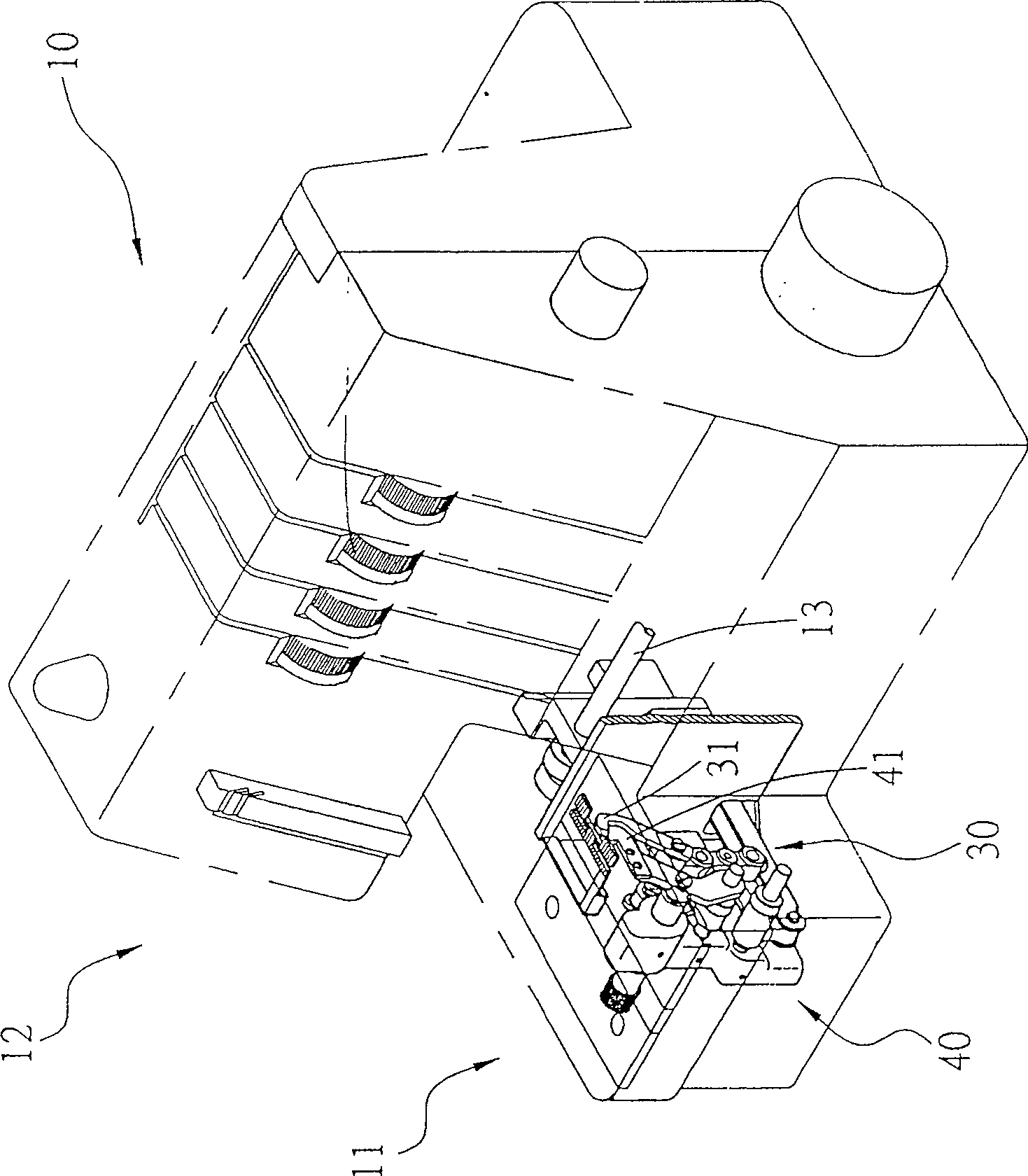
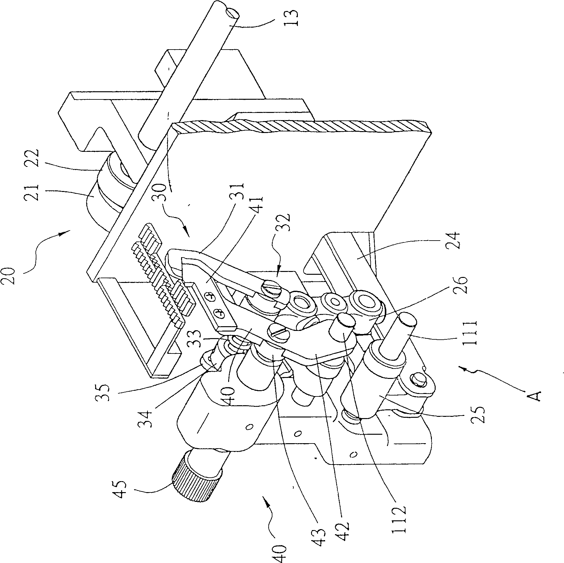
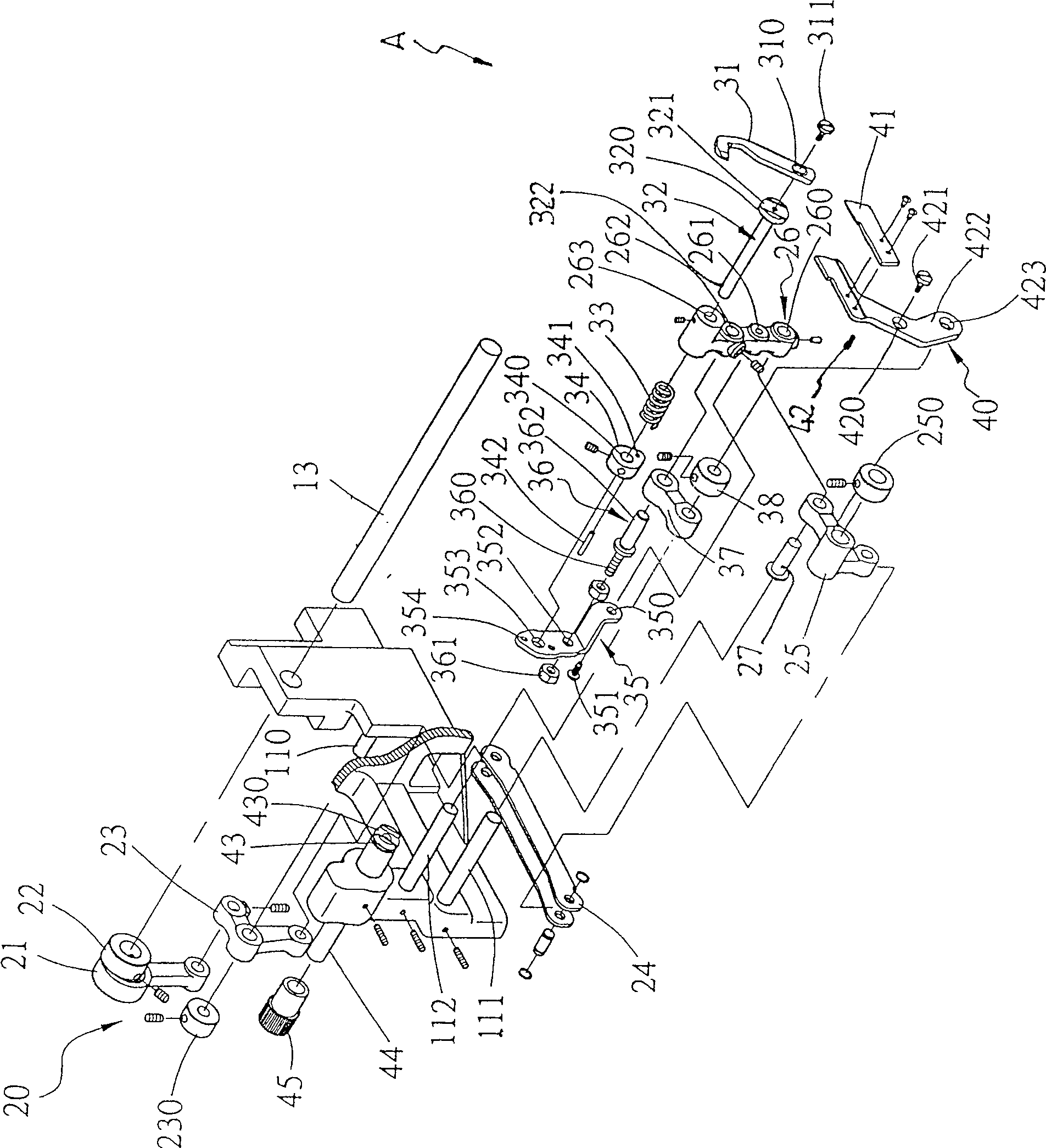
[0064] Please refer to figure 1 , 2, 3, the sewing machine 10 of the present invention, according to the embodiment shown in the accompanying drawings, has a platform-type support 11, the support 11 has a cantilever 12, and the bottom of the cantilever 12 end is provided with a bur. The cutting knife mechanism A for cutting the selvage, the frame 11 is provided with a transmission shaft 13 for power output, cooperates with the upper cutting knife transmission device 20 to drive the upper cutting knife 31 of the cutting knife mechanism A to move; and the cutting knife mechanism A is respectively provided with The upper cutting knife limiting device 30 and the lower cutting knife limiting device 40, the upper cutting knife 31 in the two devices and the lower cutting knife 41 can change their positions and ensure their changed positions; wherein, the present invention The feature is that the upper cutting knife 31 and the lower cutting knife 41 have a more stable function of mul...


PUM


Abstract

The invention relates to a sewing machine cutter device, which has upper and lower cutter seats, the upper cutter seat passes through the brake body of the upper cutter transmission device, and simultaneously passes through the elastic reset member and is fixed on the catch. The support frame on the moving body enables the upper cutter seat to obtain an excellent double support effect, and can effectively shorten the overall length of the upper cutter seat. The knife transmission device cooperates with the parallel pivot body between the brake body and the machine base, and the power steering and auxiliary parts of the knife transmission device to form a high-stability parallel four-bar linkage structure, and the lower knife is fixed on the The seat part is fixed on the knife slot, and the end slides on a parallel pivot, so that the lower knife has better resistance and is more stable, so as to achieve stability in use.

Description

technical field [0001] The invention relates to a cutting knife device of a sewing machine, in particular to a cutting knife device with an up and down motion for cutting cloth edges. Background technique [0002] At present, the edge cutting device of the sewing machine has an upper cutter that moves up and down to cut the edge of the cloth, and cooperates with a fixed lower cutter. It is stored under the table top of the machine base to facilitate the sewing operation when there is no need to cut the selvedge. Therefore, in addition to the smoothness of the upper and lower movements and the stability of the selvedge, the upper cutter needs to consider replacing the upper cutter. The convenience of the position, and for the part of the lower cutter, it is necessary to consider the movement of the position of the upper cutter to adjust the width of the selvedge, but such a structure has the following deficiencies, such as: [0003] 1. Insufficient stability of the upper cut...

Claims


Application Information

Patent Timeline
IPC IPC(8): D05B37/06
Inventor 曾贤长
Owner 曾贤长
Why Eureka
Try Eureka