Worktable locating assembly

A technology for positioning components and workbenches, applied to workbenches, manufacturing tools, etc., can solve problems such as component damage, limited use of positioning pins, and inability to perform positioning, and achieve the effect of simplified structure and stable operation

Inactive Publication Date: 2017-06-23
SUZHOU SONGSHUN HARDWARE
View PDF0 Cites 0 Cited by
  • Summary
  • Abstract
  • Description
  • Claims
  • Application Information

AI Technical Summary

Problems solved by technology

[0002] The rotary table is usually positioned by positioning pins, but the use of positioning pins is relatively limited and needs to be matched with holes at specific positions. Once a deviation occurs, positioning cannot be performed, and even parts will be damaged in severe cases.

Method used


Image

  • Worktable locating assembly

Examples


Embodiment Construction

[0011] The present invention is described below in conjunction with accompanying drawing.

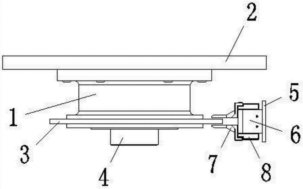
[0012] Such as figure 1 As shown, a worktable positioning assembly described in the present invention includes a main turntable 1, a worktable 2 and a positioning device; the worktable 2 is arranged on the main turntable 1, and the lower side of the main turntable 1 is arranged There is a positioning ring 3, and the lower end of the main turntable 1 is provided with a rotating connecting shaft 4; the positioning device includes a connecting plate 5, a clamping cylinder 6 and two clamping arms 7, the connecting plate 5 is fixed, and the clamping cylinder 6 is arranged on the connecting plate 5, the two ends of the clamping cylinder 6 are provided with connecting blocks 8, and the two clamping arms 7 are respectively located on the upper and lower sides of the positioning ring 3, and the two clamping arms 7 are respectively connected with the connecting blocks 8 at both ends of the clampi...


PUM


Abstract

The invention discloses a worktable positioning assembly, which comprises a main turntable, a worktable plate and a positioning device; the worktable plate is arranged on the main turntable, a positioning ring is arranged on the main turntable, and a rotating connection shaft is arranged at the lower end of the main turntable The positioning device includes a connecting plate, a clamping cylinder and two clamping arms, the connecting plate is fixed, the clamping cylinder is arranged on the connecting plate, connecting blocks are arranged at both ends of the clamping cylinder, and the two clamping arms are respectively located on the positioning ring On the upper and lower sides of the upper and lower sides, the two clamping arms are respectively connected to the connecting blocks at both ends of the clamping cylinder; the worktable positioning assembly of the present invention drives the main turntable and the worktable to rotate by the rotating connecting shaft, and after rotating to a specific position, the clamping cylinder Drive the clamp arm to clamp the positioning ring and position the worktable. The overall structure is simpler than the positioning pin structure, and the operation is stable.

Description

technical field [0001] The invention relates to a workbench positioning assembly. Background technique [0002] The rotary table is usually positioned by positioning pins, but the use of positioning pins is relatively limited and needs to be matched with holes at specific positions. Once a deviation occurs, positioning cannot be performed, and even parts will be damaged in severe cases. Contents of the invention [0003] In view of the above-mentioned existing technical problems, the object of the present invention is to propose a workbench positioning assembly. [0004] The technical solution of the present invention is realized as follows: a workbench positioning assembly includes a main turntable, a workbench and a positioning device; the workbench is arranged on the main turntable, a positioning ring is arranged on the main turntable, and The lower end is provided with a rotating connecting shaft; the positioning device includes a connecting plate, a clamping cylinder...

Claims


Application Information

Patent Timeline
Patent Type & Authority Applications(China)
IPC IPC(8): B25H1/00
CPCB25H1/00
Inventor 归杏花
Owner SUZHOU SONGSHUN HARDWARE
Why Eureka
Try Eureka