Liquid crystal display and its light source driving method
A liquid crystal display device, light source driving technology, applied to static indicators, instruments, etc., can solve problems such as misoperation of inverters, inability to turn on lights, narrow duty cycle, etc.
- Summary
- Abstract
- Description
- Claims
- Application Information
AI Technical Summary
Problems solved by technology
Method used
Image

Examples
no. 1 Embodiment
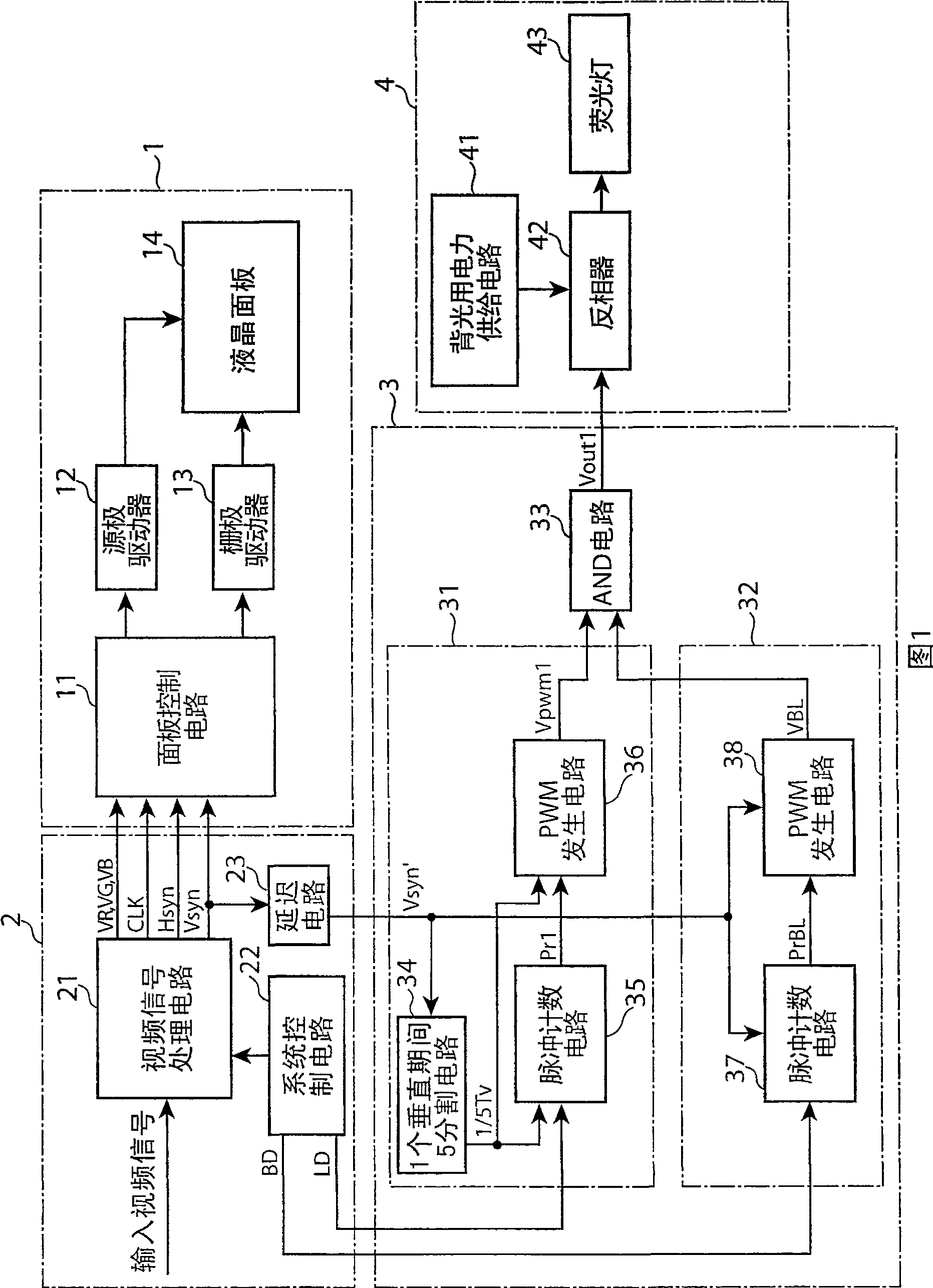
[0082] First, a liquid crystal display device according to a first embodiment of the present invention will be described. FIG. 1 is a block diagram showing the structure of a liquid crystal display device according to a first embodiment of the present invention. The liquid crystal display device shown in FIG. 1 includes a liquid crystal module 1 , a video processing unit 2 , a PWM dimming driving circuit unit 3 and a backlight unit 4 .
[0083] The video processing unit 2 includes a video signal processing circuit 21 , a system control circuit 22 and a delay circuit (delay circuit) 23 . The video signal processing circuit 21 converts an input video signal such as a video signal of a television signal into a signal suitable for processing in the liquid crystal module 1 . Specifically, the video signal processing circuit 21 outputs video signals VR, VG, VB divided into three primary colors (RGB), vertical synchronous signal Vsyn, horizontal synchronous signal Hsyn, and pixel cl...
no. 2 Embodiment
[0104] Next, a liquid crystal display device according to a second embodiment of the present invention will be described. 5 is a block diagram showing the structure of a liquid crystal display device according to a second embodiment of the present invention. The difference between the liquid crystal display device shown in FIG. 5 and the liquid crystal display device shown in FIG. 1 is that the backlight unit 4 is changed to a backlight unit 4a, and three 1 / 4 vertical period delay circuits 5a-5c are added, and the other parts Since it is the same as the liquid crystal display device shown in FIG. 1 , the same parts are given the same symbols and their descriptions are omitted, and the different parts will be described in detail below.
[0105] The 1 / 4 vertical period delay circuit 5a receives the inverter drive signal Vout1 from the PWM dimming drive circuit section 3, and outputs the inverter drive signal Vout2 delayed by 1 / 4 of the vertical period from the inverter drive sig...
no. 3 Embodiment
[0122] Next, a liquid crystal display device according to a third embodiment of the present invention will be described. Fig. 13 is a block diagram showing the structure of a liquid crystal display device according to a third embodiment of the present invention. The difference between the liquid crystal display device shown in FIG. 13 and the liquid crystal display device shown in FIG. 1 is that the system control circuit 22 is changed to a system control circuit 22a that also outputs whisker pulse (whisker pluse) limiting duty data PD, and The PWM generation unit 32 for black insertion dimming is changed to a PWM generation unit 32a for black insertion dimming that also includes a pulse width limiting circuit 39, and the others are the same as those of the liquid crystal display device shown in FIG. 1 , so the same parts are marked The same symbols are used and their explanations are omitted, and the different parts will be described in detail below.
[0123] The system cont...
PUM
 Abstract
Description
Claims
Application Information
 - R&D
- Intellectual Property
- Life Sciences
- Materials
- Tech Scout
- Unparalleled Data Quality
- Higher Quality Content
- 60% Fewer Hallucinations
Browse by: Latest US Patents, China's latest patents, Technical Efficacy Thesaurus, Application Domain, Technology Topic, Popular Technical Reports.
© 2025 PatSnap. All rights reserved.Legal|Privacy policy|Modern Slavery Act Transparency Statement|Sitemap|About US| Contact US: help@patsnap.com