Method for prolonging retention period of molten steel in RH vacuum groove

A technology of residence time and vacuum tank, applied in the field of metallurgy, can solve the problems of short residence time and long processing time

Inactive Publication Date: 2009-05-06
CHINA METALLURGICAL EQUIP SHANGHAI ENG & TECH
View PDF4 Cites 0 Cited by
  • Summary
  • Abstract
  • Description
  • Claims
  • Application Information

AI Technical Summary

Problems solved by technology

The molten steel stays in the vacuum tank for

Method used


Image

  • Method for prolonging retention period of molten steel in RH vacuum groove
  • Method for prolonging retention period of molten steel in RH vacuum groove

Examples


Embodiment Construction

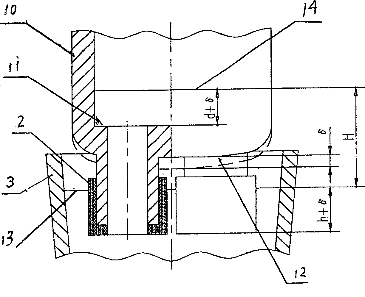
[0022] Embodiment of the present invention sees attached figure 2 :

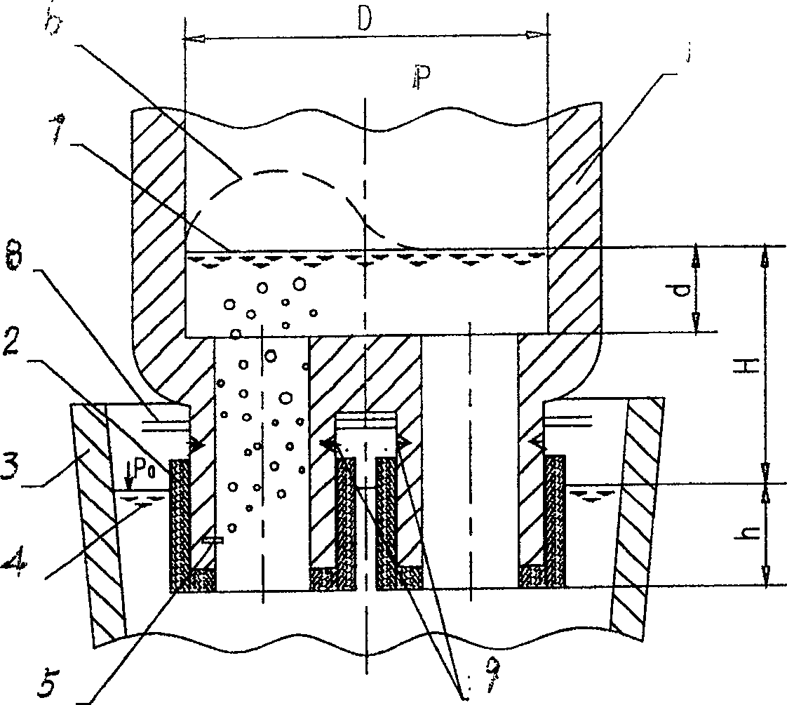
[0023] Vacuum tank, the upper part of the vacuum tank 10 is vacuum, the bottom is equipped with a dipping tube 2, and the outside of the dipping tube 2 has an unshaped refractory material, which is inserted into the molten steel in the ladle 3, wherein: the bottom of the vacuum tank 1 is planar Shallow round bottom platform 12, the inside of this shallow round bottom platform 12 has reinforcing ribs 11.

[0024] There are two dipping tubes with different opening heights in the vacuum tank, the one with the lower opening is the ascending tube, and the one with the higher opening is the descending tube.

[0025] The material at the bottom of the vacuum tank is 16Mn.

[0026] attached by figure 2 It can be seen that after changing from a spherical bottom to a shallow circular table bottom, the bottom of the vacuum tank is thinned by δ (about 100 mm). In this way, when the radiation protection plate, the w...


PUM


Abstract

The invention discloses a method to prolong residence time of liquid steel in RH vacuum tank in metallurgy domain, which is characterized by the following: adopting thin round bench bottom in vacuum tank; decreasing thickness of resistance material of the bottom of vacuum tank; replacing original 20g with material of higher intensity as bottom material; welding reinforced rib on inner of thin round bench bottom properly; assuring the strength of vacuum tank. This invention can assure liquid steel circling speed and shorten the time of RH vacuum treatment.

Description

technical field [0001] The invention relates to RH vacuum processing equipment in the field of metallurgy. It is an out-of-furnace refining method for converter steelmaking. Background technique [0002] RH is one of the most effective external refining equipment in the modern converter steelmaking process. In order to produce ultra-low carbon steel and pure steel such as IF steel, each converter steelmaking plant regards the circulation rate of molten steel (that is, the amount of molten steel entering the vacuum tank per minute) as the most important technical parameter when configuring RH equipment. The trend at home and abroad today is that the amount of circulating molten steel per minute has reached more than 75% of the molten steel capacity in the ladle. The higher the circulation rate, the better the kinetic conditions of the metallurgical reaction under vacuum. [0003] At the same time, many steel mills have not paid enough attention to another important technic...

Claims


Application Information

Patent Timeline
IPC IPC(8): C21C7/10
Inventor 金弘熙
Owner CHINA METALLURGICAL EQUIP SHANGHAI ENG & TECH
Why Eureka
Try Eureka