
Waste gas recirculation heat-exchanger

A waste gas recirculation and heat exchanger technology, applied in the direction of heat exchanger types, indirect heat exchangers, heat exchange equipment, etc., can solve the problems of low heat exchange efficiency and heat exchange effect of heat exchangers that cannot meet the requirements, and achieve Improved heat exchange efficiency, simple structure, and reduced maintenance costs

Active Publication Date: 2009-03-25
BEIJING U BRIDGE CHAOYANG +1
View PDF9 Cites 0 Cited by
  • Summary
  • Abstract
  • Description
  • Claims
  • Application Information

AI Technical Summary

Problems solved by technology

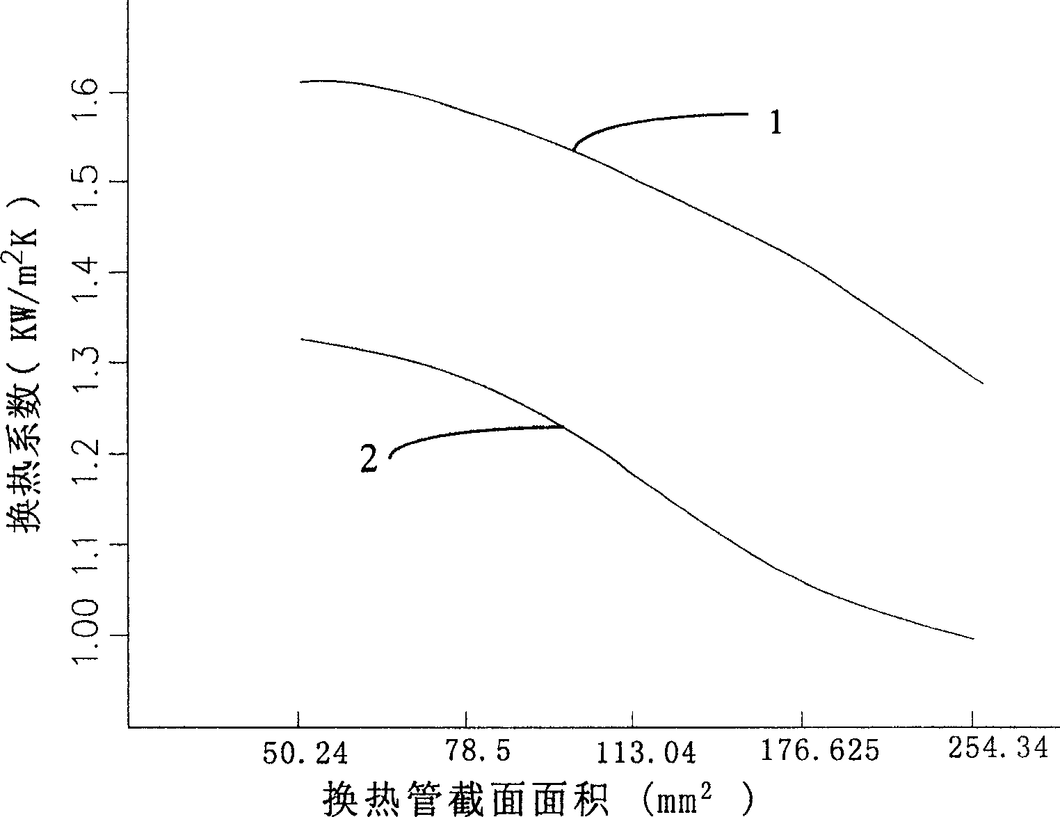
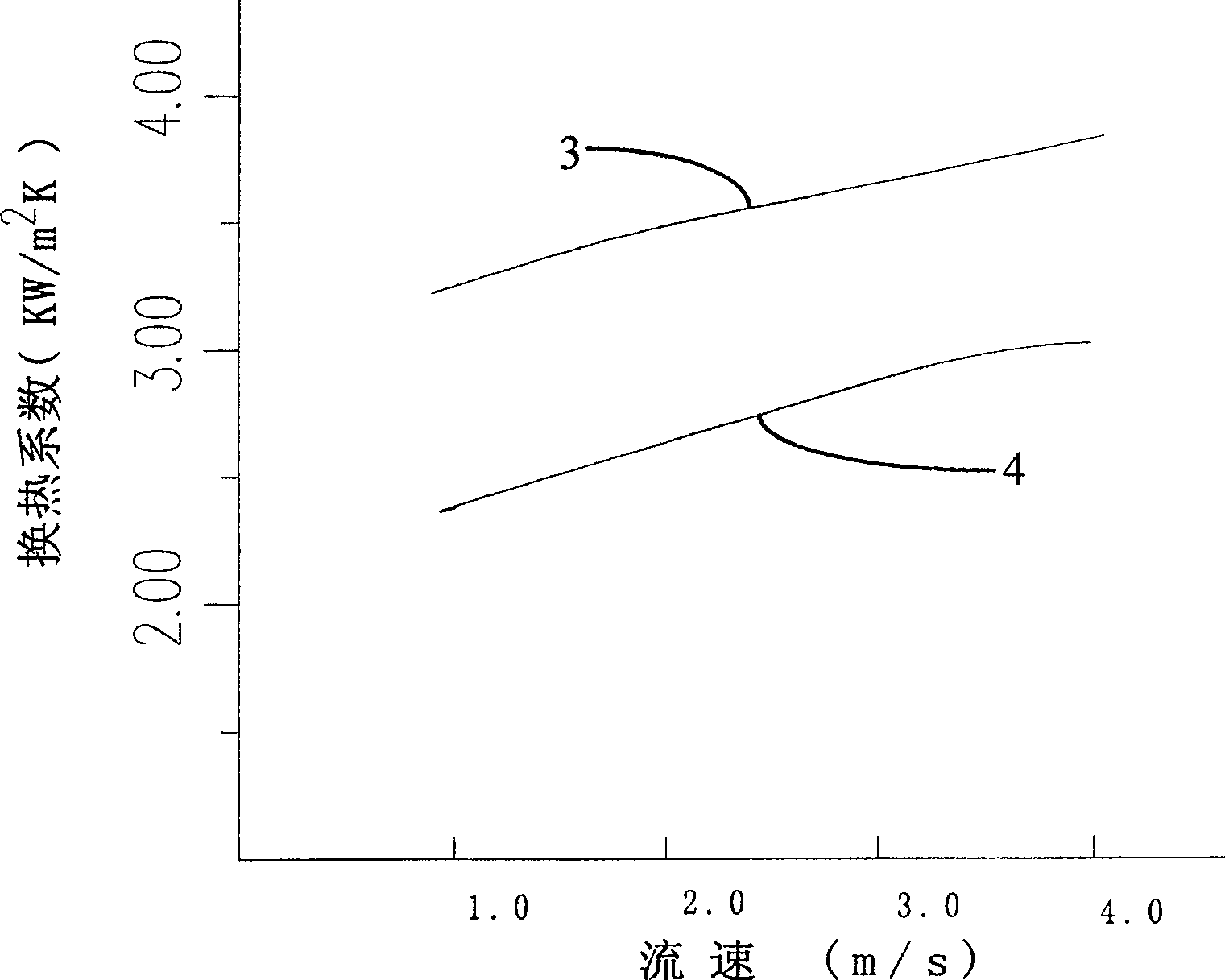
This type of heat exchanger has a simple structure, but the heat exchange efficiency is low; at present, based on the former heat exchanger, a heat exchanger with a circular cross-section with an inwardly protruding spiral groove on the surface is set. The heat exchange efficiency of the heat pipe has been relatively improved a lot, but with the increasingly stringent requirements of automobile emission standards, the heat exchange effect of this heat exchanger has gradually failed to meet the requirements

Method used


Image

  • Waste gas recirculation heat-exchanger
  • Waste gas recirculation heat-exchanger
  • Waste gas recirculation heat-exchanger

Examples


Embodiment 1

[0046] see Figure 11 , is when the shell 6 of the heat exchanger has a circular cross section, the arrangement of the heat exchange tubes 5 with a flat cross section in the shell 6; the heat exchange tubes 5 are compactly arranged in the shell, and the heat exchanger The arrangement includes sequential arrangement and staggered arrangement, and the heat exchange tubes along the shell are arranged in a ring shape at a certain angle. This arrangement is compact and can improve the heat exchange efficiency of the heat exchanger.

Embodiment 2

[0048] see Figure 12 , when the shell 6 of the heat exchanger has a rectangular cross section, the arrangement of the heat exchange tubes 5 with a rectangular cross section in the shell 6; the heat exchange tubes 5 are staggered at a certain angle, and two adjacent rows of tube bundles are symmetrical Arranged in a distributed manner, the two ends of the nozzles of the heat exchange tubes 5 are welded and fixed on the tube plates 62 at both ends of the shell 6. This arrangement makes the flow of the coolant outside the tubes intensified, thereby increasing the amount of heat exchange.

Embodiment 3

[0050] see Figure 13 , is when the shell 6 of the heat exchanger has a rectangular cross-section, the arrangement of the heat exchange tubes whose cross-sectional shapes are arc-shaped in the shell 6 . The heat exchange tubes 5 are staggeredly arranged in the housing in two ways of vertical and parallel. Such an arrangement increases the turbulence of the coolant outside the tube, which enhances the heat exchange effect inside and outside the tube.


PUM


Abstract

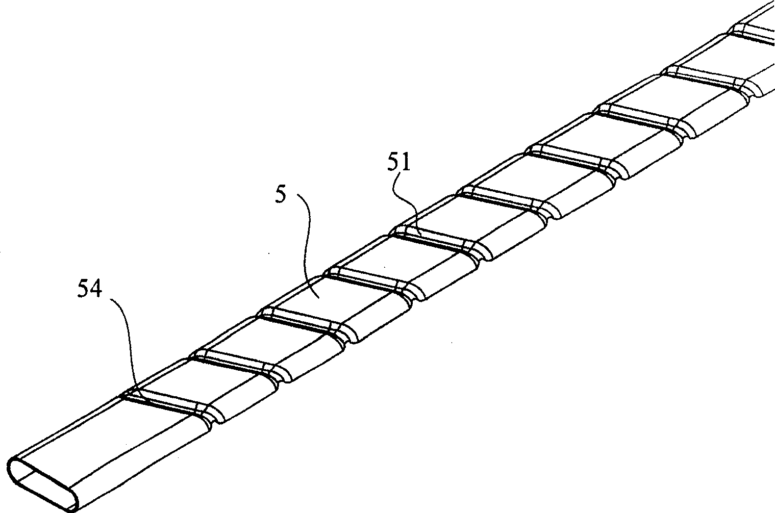
The present invention involves an exhaust gas recirculation heat exchanger, it includes: shell and heat exchanging tubes; the heat exchanging tubes are parallel each other and are fixed in the shell; the section height and the width of said heat exchanging tubes are not equal, and the shapes are flat; the outer surface of said heat exchanging tubes is equipped with groove; said groove is convex on the inner surface of heat exchanging tubes and the shapes are corresponding with the shapes of groove, the invention used in vehicle motor exhaust gas recirculation can reduce the exhaust amount of vehicle motor oxynitrides under same conditions, increase the discharging property indexes of vehicle motor. The invention also is suitable for be the middle cooling device in turbine boost system to increase the property of motor. Compared with plate-fin heat exchanger, the invention has simple structure and reduces manufacture cost. Due to the invention installs spiral convex structure on the heat exchanging tube inner wall, it increases heat exchanging and simultaneously the strong turbulence movements scours dirtiness in tubes violently, so the tubes are not easy to scaling and are beneficial for washing, the invention reduces the maintenance costs of the heat exchanging device.

Description

technical field [0001] The invention relates to a heat exchanger, in particular to a heat exchanger for an exhaust gas recirculation cooling system to reduce the emission of nitrogen oxides in automobiles; it is also suitable for use as an intercooler in a turbocharger system to improve engine performance. Background technique [0002] Heat exchangers are used in various industrial sectors such as power, metallurgy, chemical industry, oil refining, construction, machinery manufacturing, food, medicine and aerospace. Therefore, the optimal design of heat exchangers is particularly important for various industries. With increasingly stringent emission standards around the world, heat exchangers in automotive exhaust gas recirculation cooling systems are crucial. [0003] Exhaust gas recirculation cooling technology is in the well-known automobile engine exhaust gas recirculation system. Part of the exhaust gas emitted by the automobile engine is cooled and recycled through th...

Claims


Application Information

Patent Timeline
Patent Type & Authority Patents(China)
IPC IPC(8): F28D7/00F28F1/04F28F1/06
Inventor 景建周景建坤杨晓瑷汤俊洁沈董浩
Owner BEIJING U BRIDGE CHAOYANG
Learn More