
Automatic indexer for cam shaft grinder

An automatic indexing and camshaft technology, which is applied in the direction of grinding machines, abrasive belt grinding machines, grinding/polishing equipment, etc., can solve problems such as difficult to ensure consistent contour accuracy, difficult cam template technology, and poor profile consistency. Achieve the effects of reducing technical difficulty and labor intensity, reducing manufacturing difficulty, and good mold line consistency

Inactive Publication Date: 2008-12-24
HUNAN UNIV
View PDF5 Cites 0 Cited by
  • Summary
  • Abstract
  • Description
  • Claims
  • Application Information

AI Technical Summary

Problems solved by technology

[0003] In the prior art, most camshaft manufacturers still widely use mechanical profiling camshaft grinders to profile camshaft parts. The cam profile accuracy of the camshaft is directly affected by the manufacturing accuracy of the camshaft profiling plate. Domestic camshaft The production is generally processed by MXBS8312 series microcomputer-controlled high-speed powerful camshaft grinder. The cam model of the grinder corresponds to the cam on the processed product, that is to say, there are several cams on a product (processed workpiece), (such as The three-cylinder engine has six cams, the four-cylinder engine has eight cams, and the six-cylinder engine has twelve cams), and the same number of cam models processed by the reverse method must be used on the machine tool. In this industry, mechanical profiling cams The shaft grinding machine generally adopts a fixed general-purpose indexing head, and the dial and the indexing plate are mechanically connected by screws. This method makes the camshaft workpiece not close to each other after each piece of cam is processed after the camshaft workpiece is clamped once. The pattern plate automatically rotates a phase angle. There are several pieces of cams on a camshaft workpiece, and how many pieces of patterns are required to be processed on the main shaft of the machine tool. The profile consistency of the cams on the product is also poor, and it is difficult to ensure the consistency of their contour accuracy

Method used


Image

  • Automatic indexer for cam shaft grinder
  • Automatic indexer for cam shaft grinder

Examples


Embodiment Construction

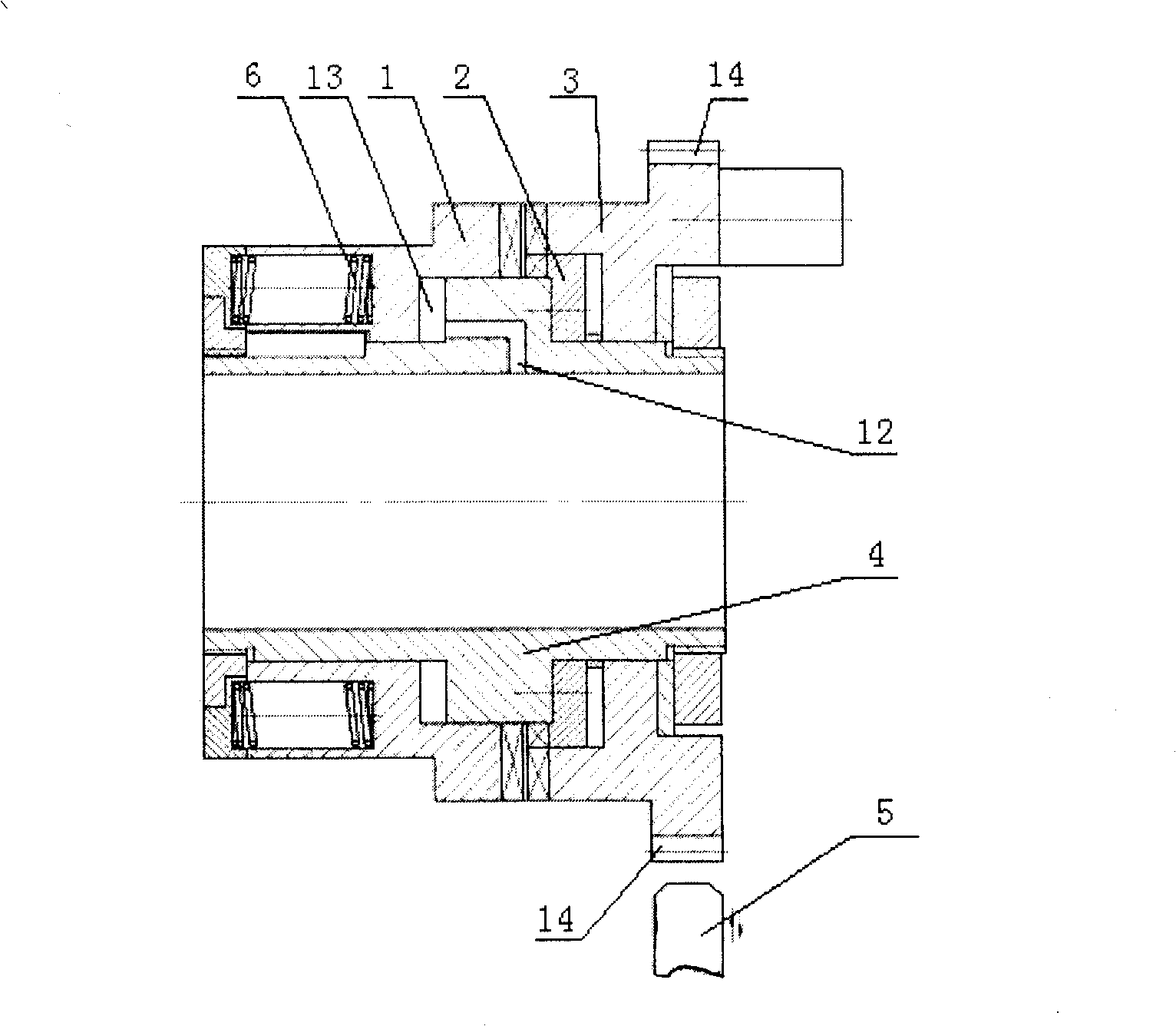
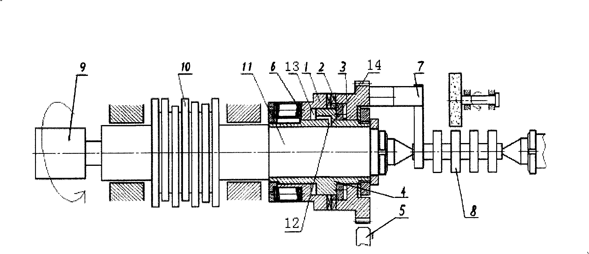
[0021] Such as figure 1 , 2 The shown device of the present invention is applied to MKS8312 numerically controlled high-speed camshaft grinding machine. The clutch mechanism adopts three face gears and the number of teeth of the first face gear 3, the second face gear 1 and the third face gear 2 is 48 teeth (it can also be determined according to The diameter of the face gear makes the number of teeth 96), and the minimum graduation is 7.5 degrees, which is the largest common divisor of the phase angles between all cams on the camshaft, which can meet the graduation requirements of the cam phase angles of all camshafts in production; The structure of the driving mechanism for the axial sliding of the two end gears 1 is that an oil chamber 13 is set between one end face of the second end face gear 1 and the hollow shaft 4 and communicates with the oil passage 12. There is a return spring 6 between the other side of the gear 1 and the axial direction of the hollow shaft 4; the ...


PUM


Abstract

The automatic indexer for cam shaft grinder includes one hollow shaft; one first contrate gear idly on the hollow shaft and with a peripheral location slot and one location pin capable of getting in and out the location slot; one second contrate gear installed onto the hollow shaft for rotating with the shaft while being capable of sliding along shaft and possessing end teeth meshing those in the first contrate gear; and a driving mechanism between the second contrate gear and the hollow shaft for the second contrate gear to slide axially. The automatic indexer may be used widely in cam shaft grinder with for the cam shaft workpiece to index automatically relatively to the explorator template, makes it possible to use the identical explorator template in grinding all the cams of the same profile in the cam shaft. It has high indexing and locating precision and other advantages.

Description

technical field [0001] The invention relates to an automatic indexing device for a camshaft grinding machine. Background technique [0002] The camshaft is one of the key components of a large-scale and wide-ranging engine. Its quality and processing accuracy directly affect the emission, energy saving and life of the engine. [0003] In the prior art, most camshaft manufacturers still widely use mechanical profiling camshaft grinders to profile camshaft parts. The cam profile accuracy of the camshaft is directly affected by the manufacturing accuracy of the camshaft profiling plate. Domestic camshaft The production is generally processed by MXBS8312 series microcomputer-controlled high-speed powerful camshaft grinder. The cam model of the grinder corresponds to the cam on the processed product, that is to say, there are several cams on a product (processed workpiece), (such as The three-cylinder engine has six cams, the four-cylinder engine has eight cams, and the six-cyl...

Claims


Application Information

Patent Timeline
Patent Type & Authority Patents(China)
IPC IPC(8): B24B19/12B24B17/02
Inventor 龙小兵沈乃良宓海青施惠明盛晓敏黄陶一
Owner HUNAN UNIV
Learn More