
Headlight for vehicle with adjustable mirror

A technology of reflectors and headlights, which is applied in the direction of headlights, lighting devices, vehicle parts, etc., can solve the problems of increased manufacturing costs and complicated metal mold structures, and achieve the effect of avoiding collisions

Inactive Publication Date: 2008-12-10
KOITO MFG CO LTD
View PDF3 Cites 3 Cited by
  • Summary
  • Abstract
  • Description
  • Claims
  • Application Information

AI Technical Summary

Problems solved by technology

[0012] However, in this Japanese Patent Application No. 2000-400085, although the above-mentioned various problems can be solved, because the ball receiving portion (engagement hole) 2b is provided on the bracket on the mirror side, the bracket structure and the mirror are molded The structure of the metal mold used is complicated, and there is a new problem of increased manufacturing cost.

Method used


Image

  • Headlight for vehicle with adjustable mirror
  • Headlight for vehicle with adjustable mirror
  • Headlight for vehicle with adjustable mirror

Examples


Embodiment Construction

[0103] Embodiments of the present invention will be described below based on examples.

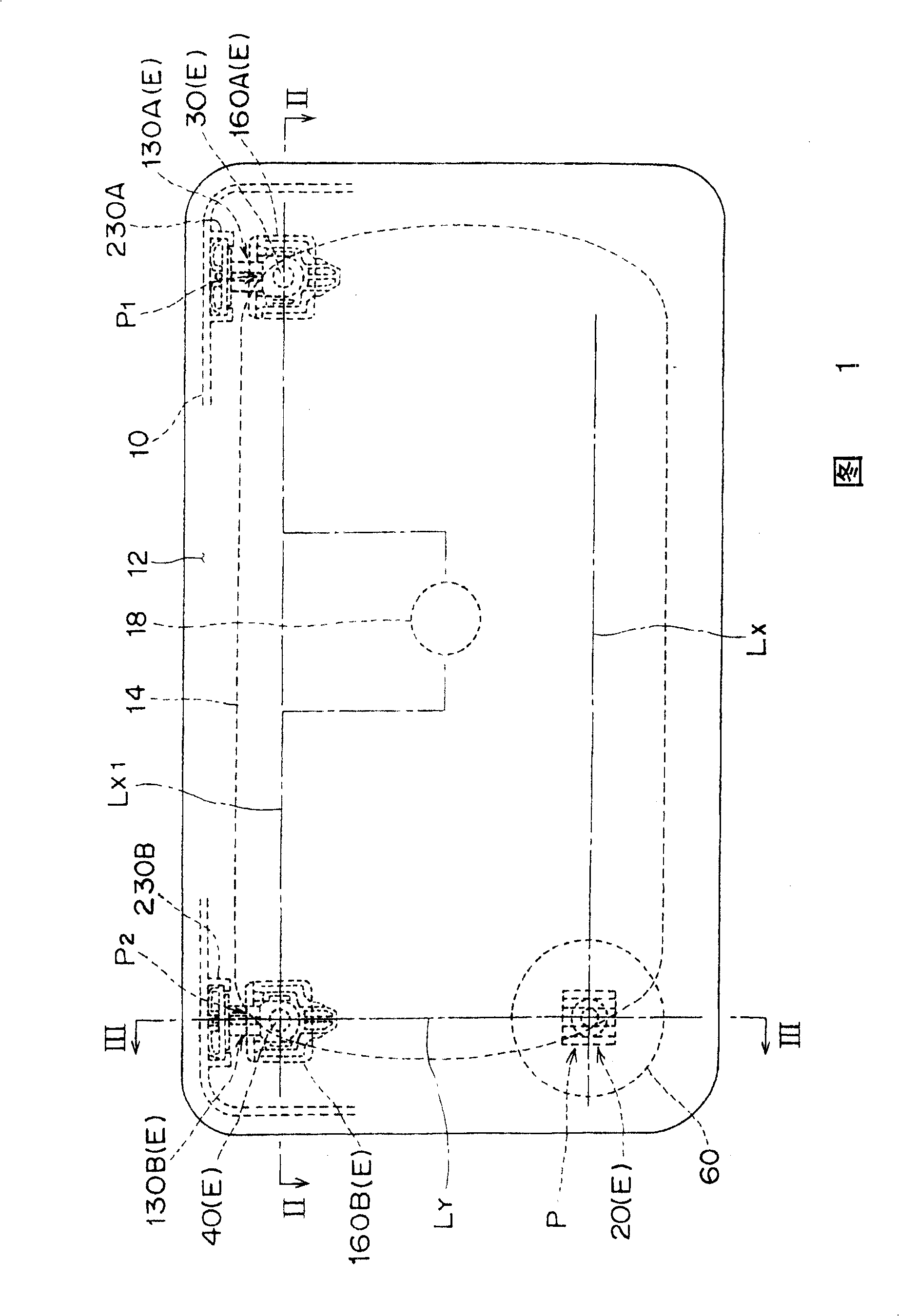
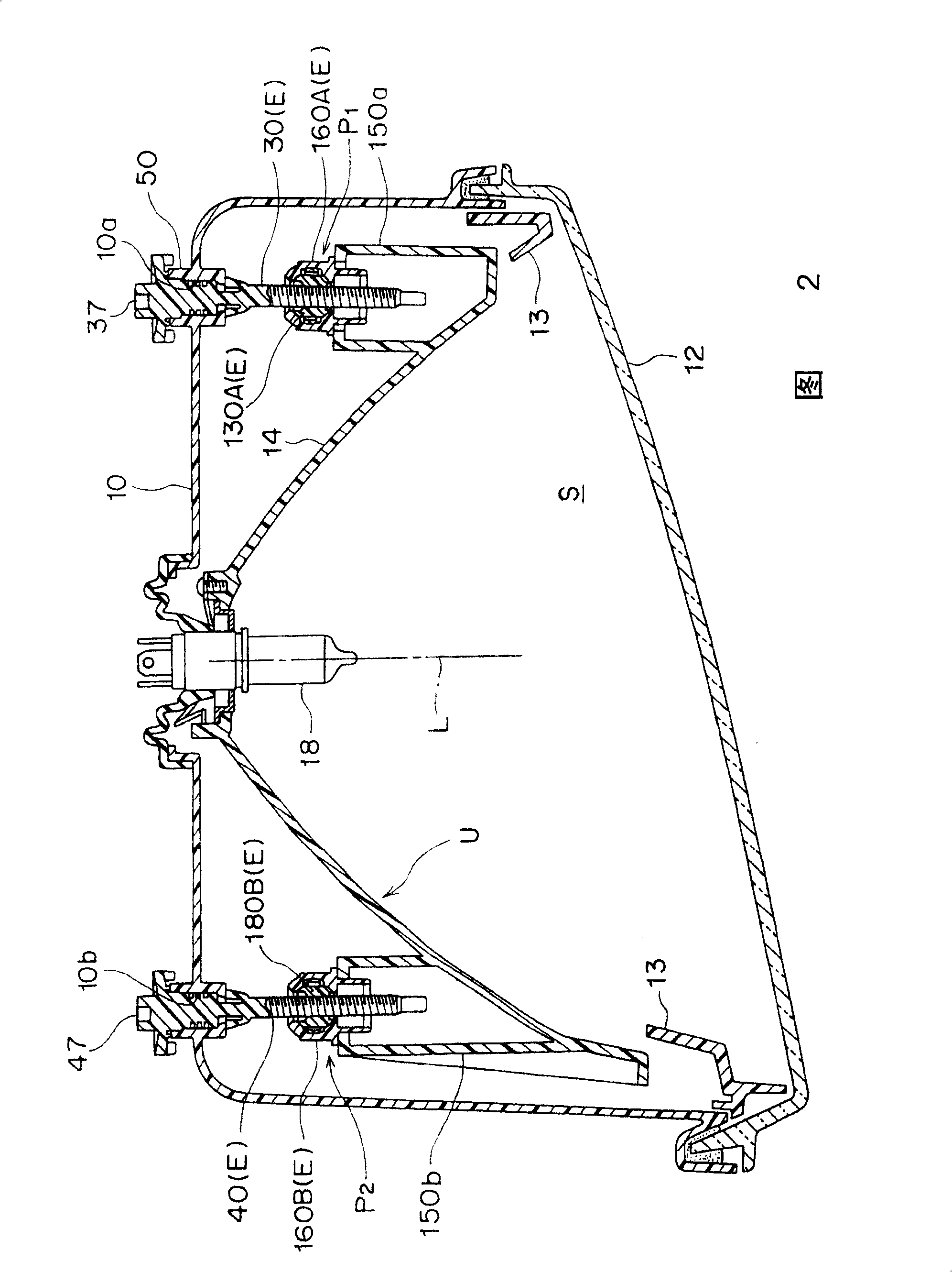
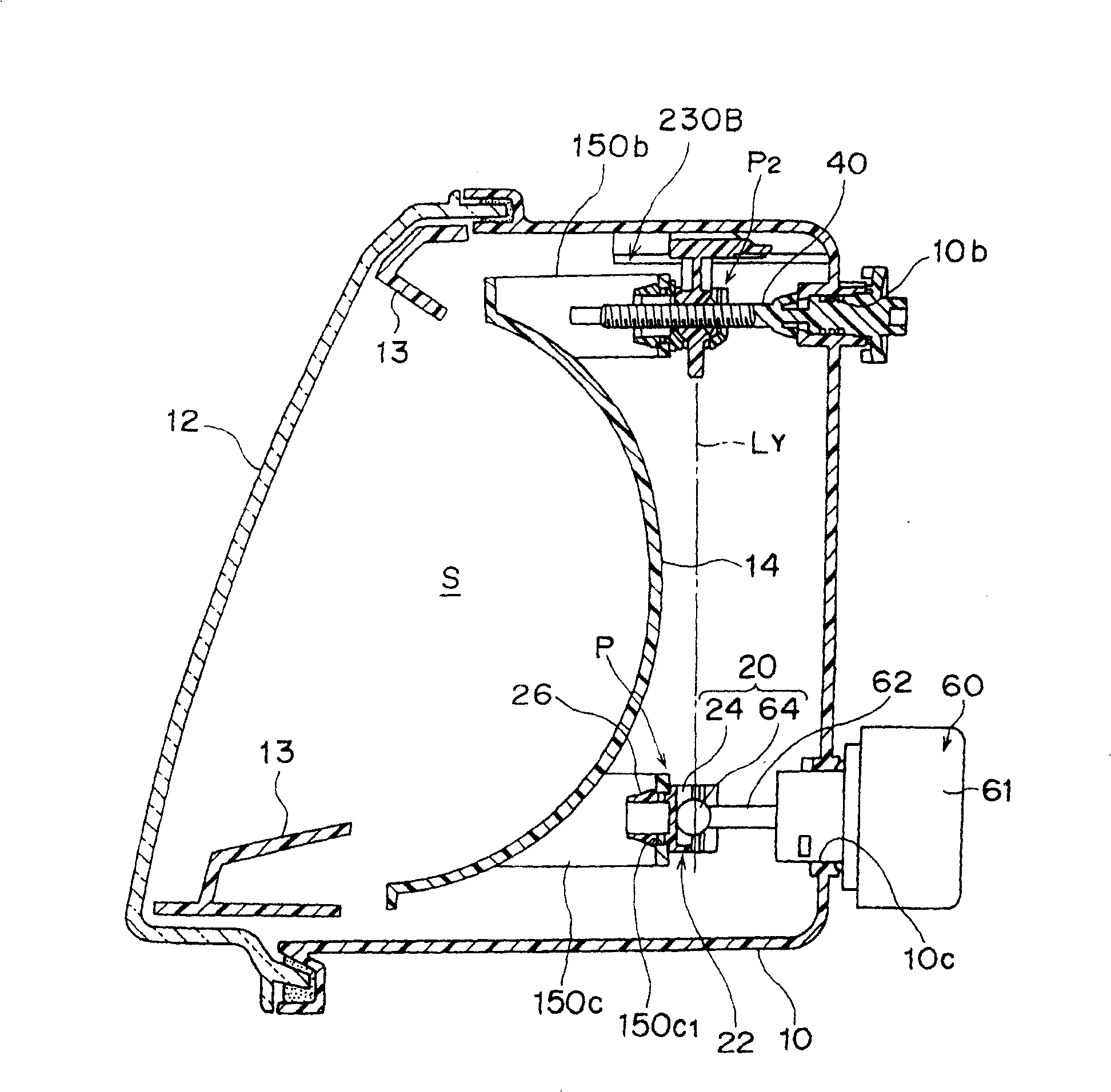
[0104] Figure 1~ Figure 16 Show the 1st embodiment of the present invention, Fig. 1 is the front view of the reflector movable type automobile headlamp of the 1st embodiment of the present invention, Fig. 2 is the horizontal sectional view of this headlamp (along Fig. The profile of the II-II line), image 3 It is a longitudinal sectional view of the headlamp (the sectional view along the III-III line shown in Fig. 1), and Fig. 4 is an exploded perspective view of the lamp body, reflector and dimming mechanism, Figure 5 It shows the cylindrical part which comprises the rotation support part of a dimming screw, (a) is an enlarged perspective view of this cylindrical part, (b) is an enlarged vertical cross-sectional view of this cylindrical part. Figure 6 Indicates the dimming screw, (a) is the enlarged perspective view of the dimming screw, (b) is the enlarged side view of the dimming ...


PUM


Abstract

A headlamp for automobiles with a movable reflector, comprising: a lamp body and a front lens for dividing a lamp chamber; a reflector housed in the lamp chamber and equipped with a light source; A dimming mechanism that can tiltably support the reflector. The dimming mechanism is composed of a dimming fulcrum, a dimming screw, and a nut member that is installed on the reflector and screwed with the dimming screw. The nut is guided by a sliding guide formed on the lamp body. The component is provided with a stress relief device with a spherical coupling structure at the mounting part of the nut component and the bracket. The ball part of the ball joint is formed on the body of the nut member on which the female thread part is formed, the slider supported by the slide guide is integrally formed on the side of the ball part, and the nut is supported by the ball housing part of the bearing attached to the bracket. The spherical part of the component. Therefore, it is possible to provide a movable reflector type automotive headlamp which reliably prevents reflector vibration, ensures smooth return of the dimming bolt, and has a simple reflector shape and mold structure for forming the reflector.

Description

technical field [0001] The present invention relates to a reflector movable type automotive headlight in which a reflector equipped with a light source is tiltably supported by a light adjusting mechanism relative to the lamp body, and in particular relates to a nut sliding guide formed on the lamp body that is connected with the light adjustment The mechanism member is a light adjusting fulcrum member screwed with a light adjusting screw, that is, a nut member, which is a movable reflector automotive headlamp. Background technique [0002] Conventional headlights for automobiles with movable reflectors such as Figure 30 As shown, on the front side of the synthetic resin lamp body 1, the synthetic resin reflector 2 integrated with the light source installation is composed of an inclined fulcrum, that is, a spherical coupling, and is screwed with two dimming screws respectively, and can move forward and backward in the axial direction. The moving fulcrum is supported by the ...

Claims


Application Information

Patent Timeline
Patent Type & Authority Patents(China)
IPC IPC(8): F21S8/10F21V14/04B60Q1/04B60Q1/06B60Q1/068B60Q1/076F21W101/10F21Y101/00
CPCB60Q1/0683B60Q1/076B60Q2200/32F21S43/50B60Q1/06
Inventor 中沢秀昭立岩丈幸西谷典弘白井克忠
Owner KOITO MFG CO LTD
Learn More