Depletion type terminal protection structure

A terminal protection structure and depletion-type technology, which is applied in the direction of electrical components, electric solid devices, circuits, etc., can solve the problems of large area of ​​traditional structures, achieve good anti-interference, save chip area, improve withstand voltage effect and reliability Effect

Inactive Publication Date: 2008-12-03
SUZHOU POWERON IC DESIGN
View PDF5 Cites 0 Cited by
  • Summary
  • Abstract
  • Description
  • Claims
  • Application Information

AI Technical Summary

Problems solved by technology

[0004] The traditional structure is widely used in power devices, however, in some applications, the traditional structure will be limited by the cost, because the traditional structure generally has a relatively large area

Method used


Image

  • Depletion type terminal protection structure
  • Depletion type terminal protection structure
  • Depletion type terminal protection structure

Examples


Embodiment Construction

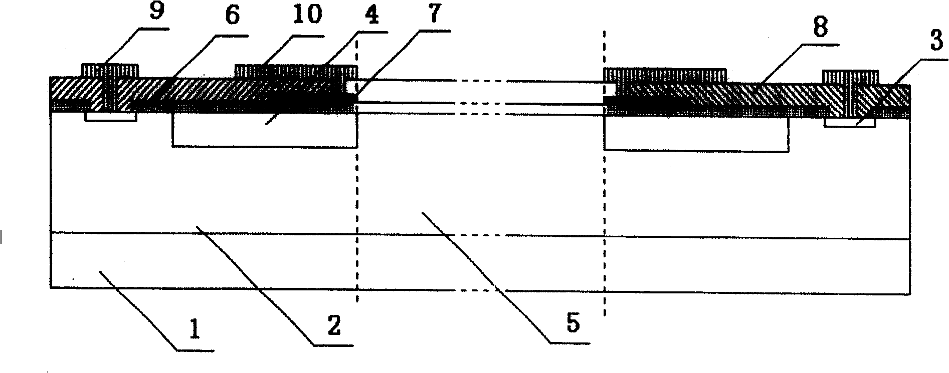
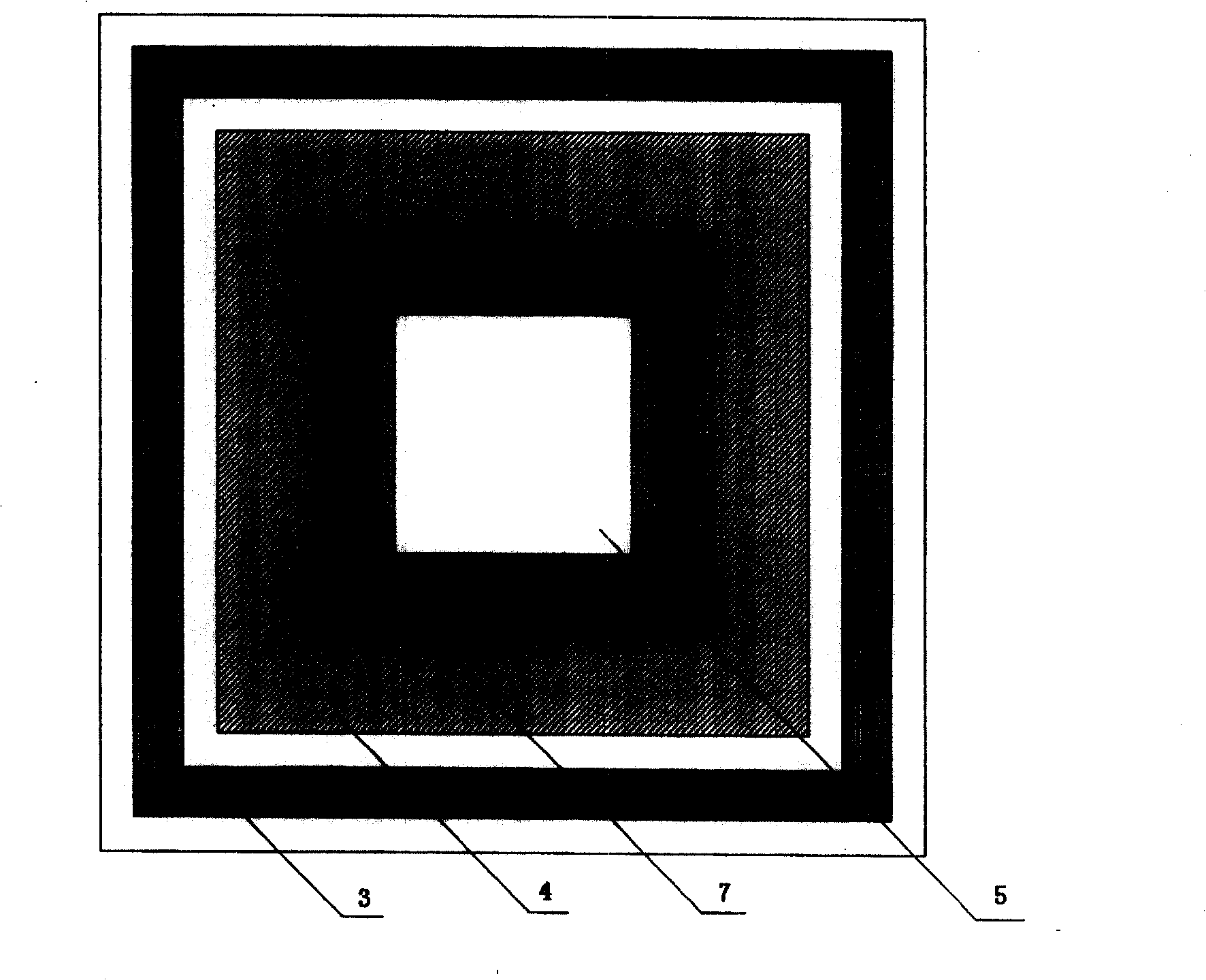
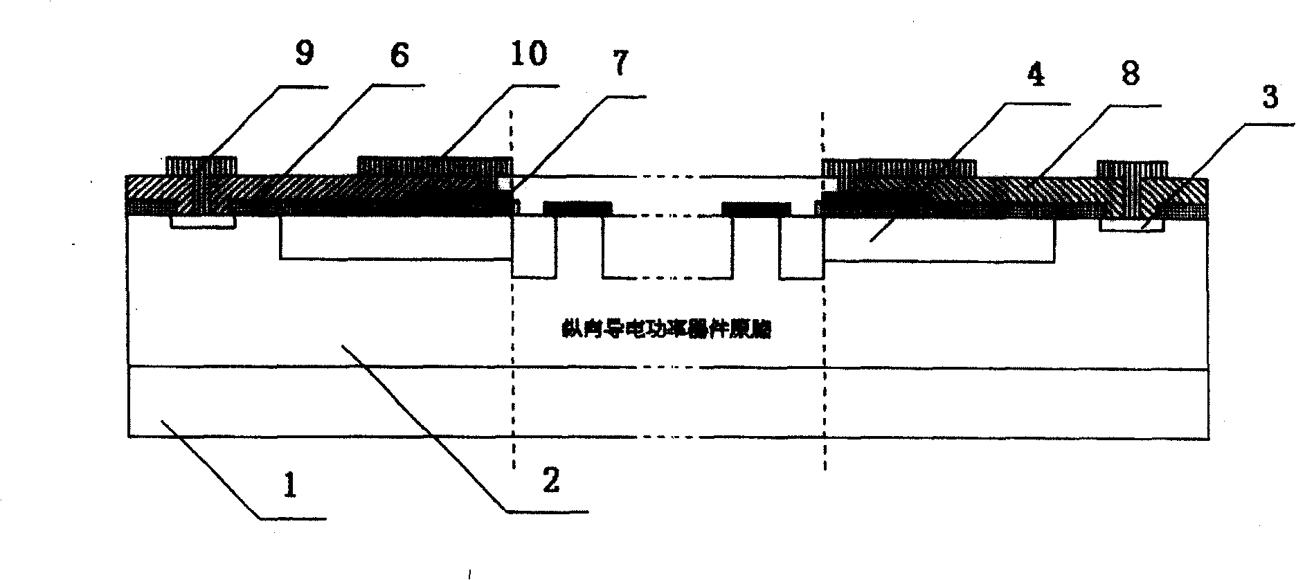
[0020] A depletion terminal protection structure for protecting power integrated circuits or power devices, comprising: a heavily doped N-type substrate 1, on which a lightly doped N-type epitaxy 2 is arranged, A heavily doped N-type stop ring 3 and a cavity 5 for setting power integrated circuits or power device cells are provided on the lightly doped N-type epitaxy 2, and the heavily doped N-type epitaxy on the lightly doped N-type epitaxy 2 A field oxide layer 6 is provided above the stop ring 3 and the area other than the original cell cavity 5, and a polycrystalline field plate 7 is provided above the field oxide layer 6. On the field oxide layer 6, the heavily doped N-type stop ring 3 and the polycrystalline field The plate 7 is covered with a dielectric layer 8, the heavily doped N-type stop ring 3 and the polycrystalline field plate 7 are respectively connected with metal leads 9, 10, and the lightly doped N-type epitaxy 2 is provided with a light Doped P-type well 4 ,...


PUM


Abstract

This invention relates to wear out terminal protection structure to protect power integration circuit or power parts, which comprises the following parts: mixture N shape underlay with N shape extension and N shape terminal ring to set power integration circuit or power original chamber; the N shape extension terminal ring and chamber area top are set with field oxidation layer with multiple crystal field boards and medium layer on board.

Description

technical field [0001] The invention relates to a protection structure, in particular to a depletion terminal protection structure for protecting power integrated circuits or power devices. Background technique [0002] The terminal structure is one of the core technologies in power devices and power integrated circuits. The quality of the terminal structure directly affects the maximum operating voltage, leakage current, reliability and stability of power devices and power integrated circuits. [0003] Figure 5 The traditional power device and power integrated circuit terminal structure are given. The structure mainly includes the following parts: (1) heavily doped P-type well, (2) polycrystalline field plate structure, and (3) N+ type stop ring. In practical applications, several heavily doped P-type wells are fabricated around the chip, and the width and spacing of the P-type wells are adjusted, and the field plate structure on the auxiliary P-type wells is used to achi...

Claims


Application Information

Patent Timeline
Patent Type & Authority Patents(China)
IPC IPC(8): H01L23/58
Inventor 易扬波李海松
Owner SUZHOU POWERON IC DESIGN
Why Eureka
Try Eureka