
Improved process for forming plastic clothes rack

A hanger and plastic technology, which is applied in the molding field of making plastic hangers, can solve the problems of insufficient filling of the distal cavity, affecting the appearance of the hanger, and large injection pressure loss, etc., to achieve shortened cooling molding time, beautiful appearance, and easy injection short distance effect

Inactive Publication Date: 2008-12-03
章辉敏
View PDF2 Cites 0 Cited by
  • Summary
  • Abstract
  • Description
  • Claims
  • Application Information

AI Technical Summary

Problems solved by technology

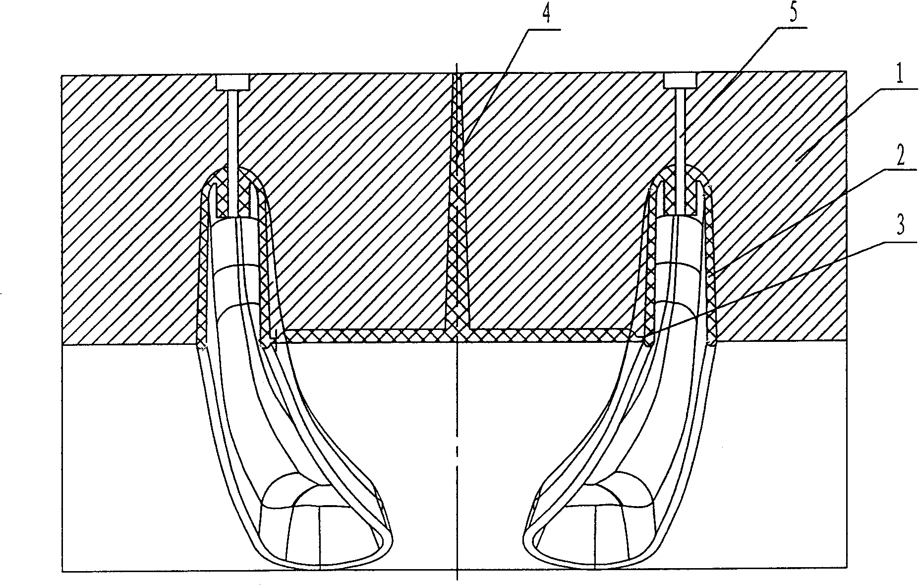
Due to the long gate runner, the molten plastic needs to be injected from gate 3 along an inverted U-shaped path, and the injection pressure loss is large, resulting in insufficient filling of the cavity at the far end from the gate, uneven thickness of the product, and affecting quality ;Because the gate runner is long, the cooling time is relatively prolonged, and the work efficiency is low; there are many waste materials, the cost is high, and the scars left after the gate is cut also affect the appearance of the hanger

Method used


Image

  • Improved process for forming plastic clothes rack
  • Improved process for forming plastic clothes rack
  • Improved process for forming plastic clothes rack

Examples


Embodiment Construction

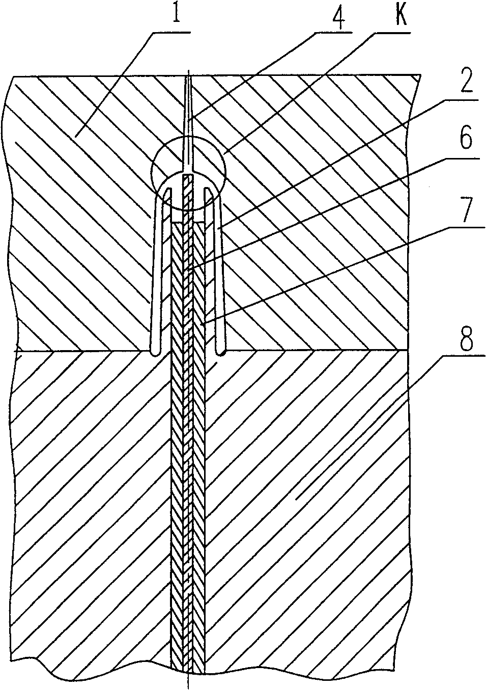
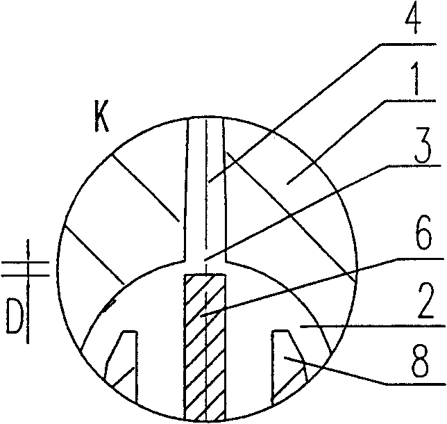
[0011] refer to figure 2 , image 3 , the hanger plastic mold of the present invention mainly contains cavity mold 1 and core mold 8, and the gap between the two forms the clothes hanger cavity 2 after fastening, and the gate 3 is located at the mold of the hanger hook hole corresponding to the cavity 2. The position of the cavity mold, the top of the cavity mold 1 and the gate 3 are connected by the gate runner 4, and the gate runner 4 replaces the core-pulling channel used to form the hanger hole in the prior art. The injection molding process is the same as the existing technology for making clothes hangers, the difference is that after the mold is closed, the molten plastic is injected from the top of the cavity mold 1, through the gate runner 4, and then injected from the gate 3 on the top of the hanger cavity 2 In the hanger cavity 2, open the mold after curing according to the routine. Since the injection starts from the top of the inverted U-shaped section of the ha...


PUM


Abstract

The invention relates to a plastic injection technique, especially the improvement for molding plastic coat hanger, wherein the section chamber mould and section core mould can be closed and separated; when they are closed, they form the coat hanger section chamber between them; pouring the fused plastic from the top of section chamber mould, via the pour open at the top into the coat hanger section chamber, to be solidified and remove the mould; then slicing the plastic coat hanger, and drilling the thin layer at hook hole at the slicing cut. The invention can improve the producing efficiency and reduce the waste material.

Description

technical field [0001] The invention relates to plastic injection molding technology, in particular to a molding method for making plastic hangers. Background technique [0002] Refer to the shape of the existing mainstream plastic hangers figure 1 As shown, its cross-section is inverted U-shaped. Clothes hanger injection mold is mainly made up of cavity mold 1 and core mold, is shaped on sprue runner 4 in cavity mold. The existing hanger injection molding method is: the gate 3 of the mold is located on one side of the inverted U-shaped bottom, and the cavity mold position at the top of the hanger cavity 2 is shaped on a core-pulling channel 5 for forming the hanger hook hole. Due to the long gate runner, the molten plastic needs to be injected from gate 3 along an inverted U-shaped path, and the injection pressure loss is large, resulting in insufficient filling of the cavity at the far end from the gate, uneven thickness of the product, and affecting quality ; Because t...

Claims


Application Information

Patent Timeline
Patent Type & Authority Patents(China)
IPC IPC(8): B29C45/27B29C45/33B29C45/38B29L31/00
Inventor 章辉敏卢志勇
Owner 章辉敏
Learn More