
Self-correcting circuit for mismatch capacity

An automatic correction and circuit technology, which is applied in the direction of circuits, electrical components, electric solid devices, etc., can solve the problems of increasing the complexity of circuit design, large area of ​​digital circuit hardware implementation, and high circuit complexity

Inactive Publication Date: 2008-11-12
PROLIFIC TECH INC
View PDF5 Cites 0 Cited by
  • Summary
  • Abstract
  • Description
  • Claims
  • Application Information

AI Technical Summary

Problems solved by technology

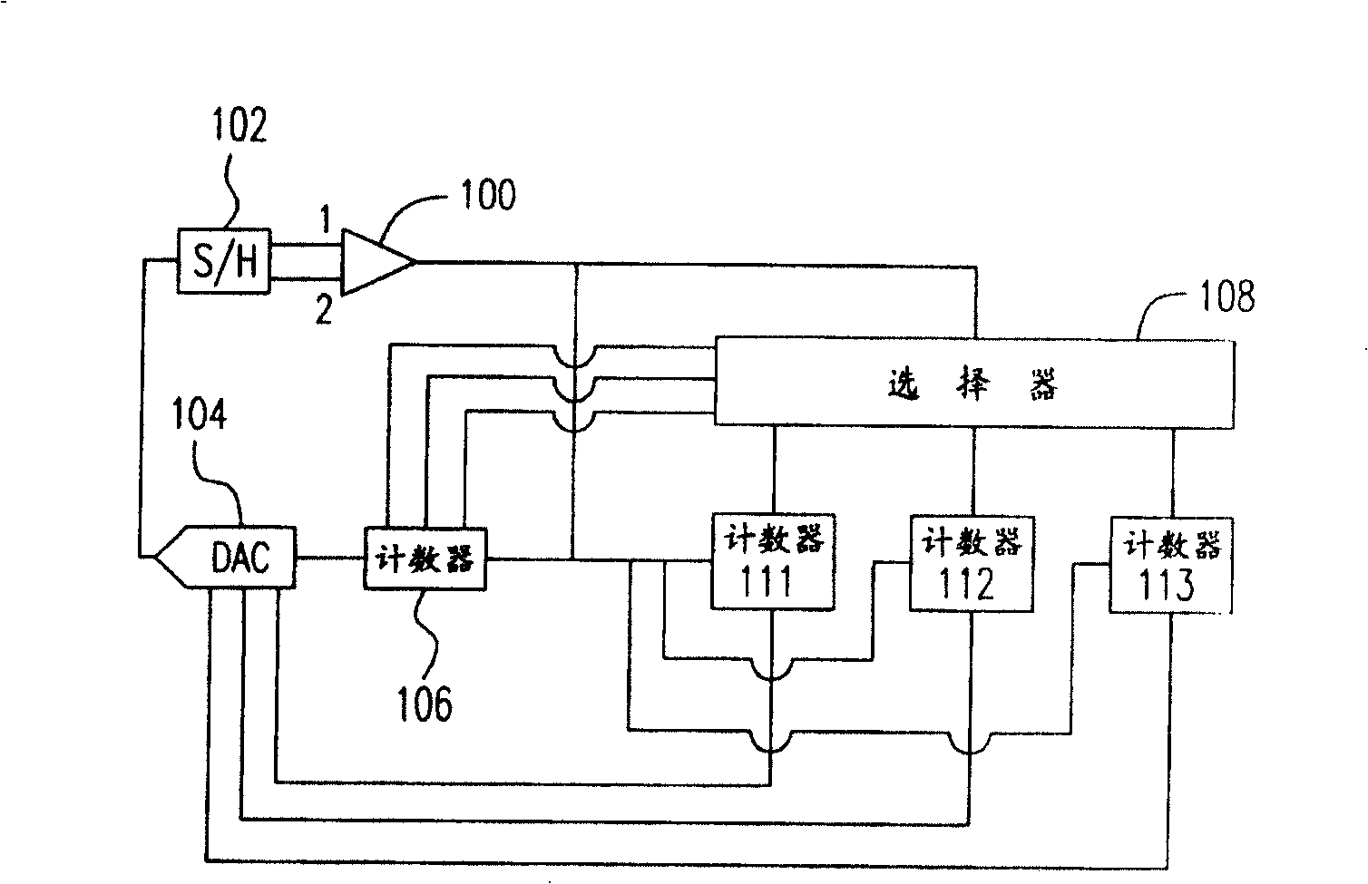
[0005] First, the original design requires a sample hold and switching circuit 102, which includes an S / H circuit and a switching circuit at any time, which increases the complexity of the circuit design
[0006] Second, the DAC 104 must generate multiple analog voltages corresponding to the digital codes for comparison. The voltage source and accuracy of this design are problems, and the circuit complexity is high
[0007] Third, this method needs to perform complicated correction steps for each digital code, the required clock pulse operation time is long, and the hardware implementation area of ​​the digital circuit is relatively large

Method used


Image

  • Self-correcting circuit for mismatch capacity
  • Self-correcting circuit for mismatch capacity
  • Self-correcting circuit for mismatch capacity

Examples


Embodiment Construction

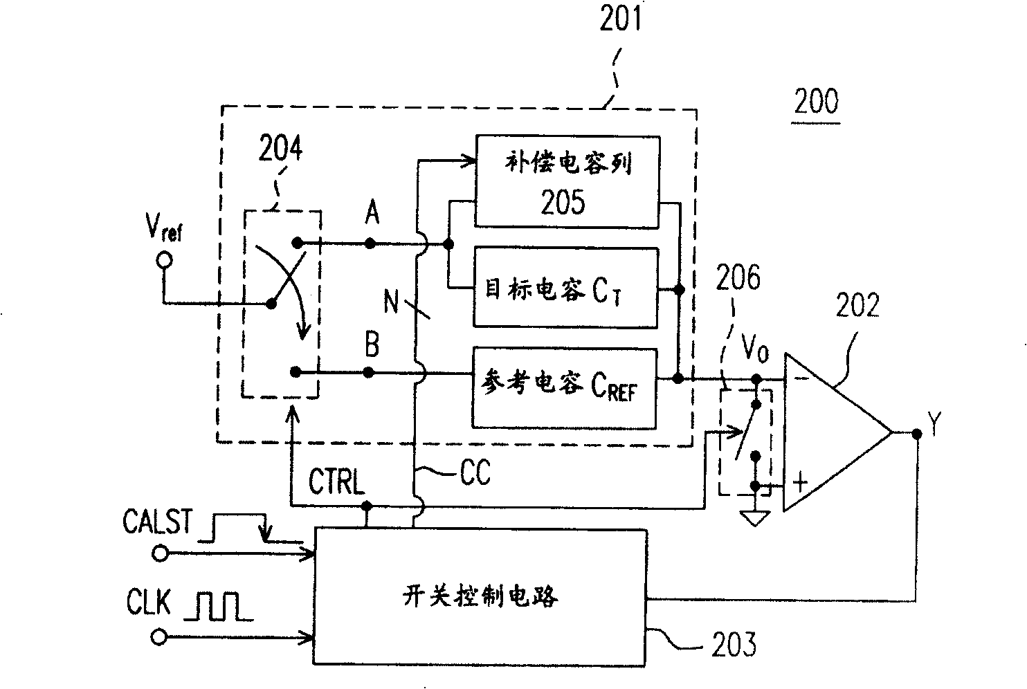
[0058] figure 2 It is a structural diagram of a capacitance mismatch automatic correction circuit 200 according to an embodiment of the present invention. The structure of the auto-calibration circuit 200 will be described below first, and then its operation flow will be described in detail.

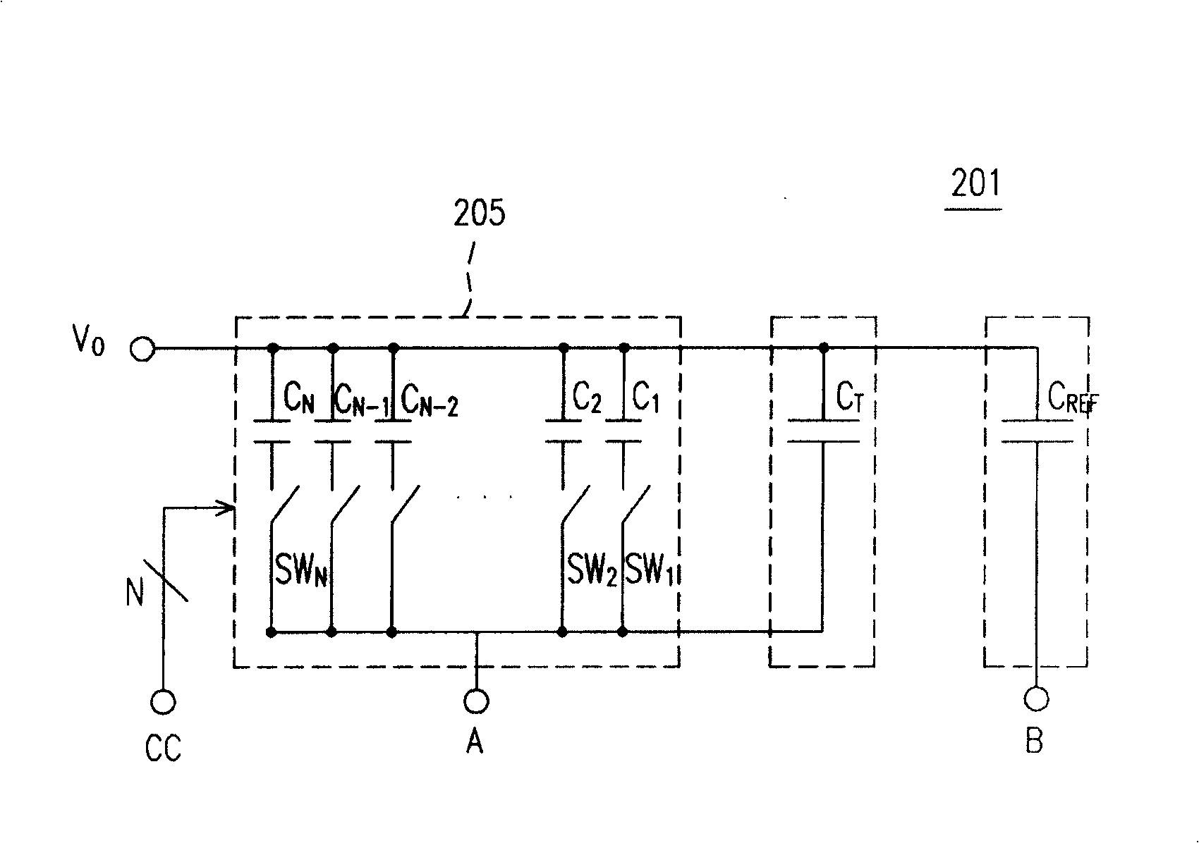
[0059] The automatic calibration circuit 200 mainly includes a sample-and-hold circuit 201 , a comparator 202 , and a switch control circuit 203 . Wherein, the sample hold circuit 201 includes a switch 204, a compensation capacitor column 205, a target capacitor C T , and the reference capacitor C REF , and provide the output voltage Vo.

[0060] The switch 204 is controlled by a switch control signal CTRL. If the switch control signal CTRL is in the first state (logic 1 in this embodiment), the switch 204 conducts the reference voltage Vref and the contact B; if the switch control signal CTRL is in the second state (logic 0 in this embodiment), Then the switch 204 conducts the refer...


PUM


Abstract

The invention relates to a capacity unmatched automatic correct circuit, which comprises sampling hold circuit, comparer, and switch control circuit, wherein the sampling hold circuit comprises compensating capacitor array, target capacity, and reference capacity, to provide output voltage; said output voltage is the calculation result of equivalent capacitor, target capacitor, and reference capacitor; the comparer via the output voltage of sampling hold circuit provides compare signal; the switch control circuit provides compensating control signal to the compensating capacitor array ton control the equivalent capacitor of said array, and in each period of time pulse signal, based on the compare signal, adjusts the compensating control signal, adds target capacitor on the equivalent capacitor, to reach reference capacitor along the time pulse signal.

Description

technical field [0001] The present invention relates to a capacitance mismatch automatic correction circuit, and in particular to a progressive capacitance mismatch automatic correction circuit. Background technique [0002] In integrated circuits, matching of capacitance values ​​is often an important design consideration. Such as switch-capacitor circuit (switch-capacitor circuit) and digital-to-analog converter (DAC: digital-to-analog converter), etc., may limit the performance of the circuit due to capacitance mismatch caused by process offset, causing the circuit to fail to perform original design level. Therefore, for integrated circuit design, how to compensate the capacitance mismatch caused by the process shift, so that the designed circuit can exert its original effectiveness and accuracy is an important key. [0003] Most of the conventional technologies use an additional capacitor array formed in parallel with the original capacitor to compensate for the mismat...

Claims


Application Information

Patent Timeline
Patent Type & Authority Patents(China)
IPC IPC(8): H01L27/00H01L29/92H03H11/00
Inventor 陈宣帆
Owner PROLIFIC TECH INC
Learn More