Electro-optical display device and electronic apparatus comprising such a device

A technology for electro-optical devices and data lines, which is applied to televisions, electrical components, color televisions, etc., can solve problems such as lowering display quality, and achieve the effect of lowering display quality.

Inactive Publication Date: 2008-11-12
SEIKO EPSON CORP
View PDF8 Cites 0 Cited by
  • Summary
  • Abstract
  • Description
  • Claims
  • Application Information

AI Technical Summary

Problems solved by technology

[0005] However, in the case of the phase expansion driving method, since a plurality of data lines are selected at the same time, it is easy to cause a phenomenon that the display quality is lowered.

Method used


Image

  • Electro-optical display device and electronic apparatus comprising such a device
  • Electro-optical display device and electronic apparatus comprising such a device
  • Electro-optical display device and electronic apparatus comprising such a device

Examples


Embodiment Construction

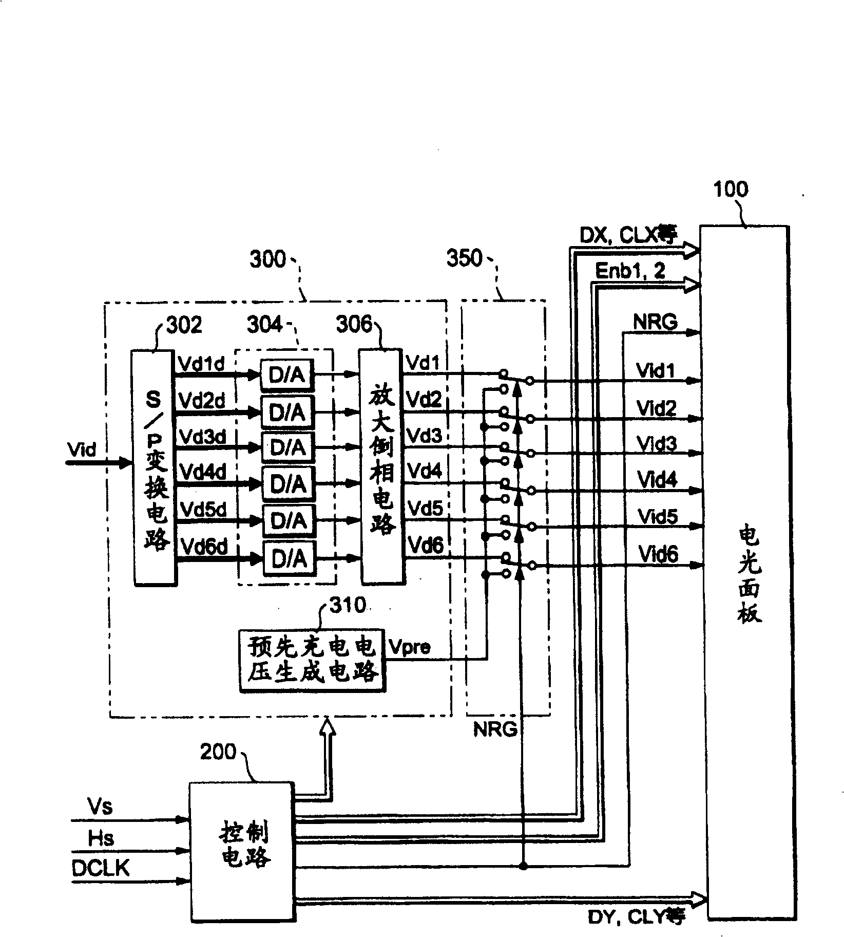
[0025] Hereinafter, preferred modes for carrying out the present invention will be described with reference to the accompanying drawings. figure 1 It is a block diagram showing the overall configuration of an electro-optical device according to an embodiment of the present invention.

[0026] As shown in the figure, the electro-optical device includes an electro-optic panel 100 , a control circuit 200 and a processing circuit 300 .

[0027] Among them, the control circuit 200 generates timing signals and clock signals for controlling each part according to the vertical scanning signal Vs, the horizontal scanning signal Hs and the dot clock signal DCLK supplied from a host device not shown in the figure.

[0028] The processing circuit 300 is further composed of an S / P conversion circuit 302 , a D / A converter group 304 , and an amplification and inversion circuit 306 .

[0029] Among them, the S / P conversion circuit 302 serially supplies from the host device in synchronization...


PUM


Abstract

Signals are respectively output from a first stage and a last stage in a shift register to which a plurality of latch circuits are connected to each other. Based on the signals, data lines are selected. A dummy pixel region comprising pixels corresponding to the selected data lines and data lines adjacent to the selected data lines becomes a non-display region. Therefore, degradation of image quality is suppressed.

Description

technical field [0001] The present invention relates to a technique for suppressing a decrease in display quality that occurs when a plurality of data lines are grouped and driven. Background technique [0002] In recent years, projectors that form small images using electro-optic panels such as liquid crystals and enlarge and project the small images on screens, walls, etc. through optical systems have become popular. This projector does not have a function of creating images by itself, but receives supply of image data (or image signals) from a host device such as a personal computer or a TV tuner. This image data specifies the gradation (brightness) of pixels, and is supplied in the form of vertical scanning and horizontal scanning of pixels arranged in a matrix, and thus is also suitable for driving an electro-optic panel used in a projector. Therefore, in electro-optic panels used in projectors, a so-called dot-by-dot method is generally adopted. In this method, scanni...

Claims


Application Information

Patent Timeline
Patent Type & Authority Patents(China)
IPC IPC(8): G02F1/133G09G3/36G09G3/20G09G3/34H04N5/66
CPCG09G2310/027G09G2310/0297G09G3/3688G09G2352/00G09G3/20G09G3/36
Inventor 村出正夫
Owner SEIKO EPSON CORP
Why Eureka
Try Eureka