Display device

A display device and display panel technology, applied in the direction of instruments, light guides, optics, etc., can solve the problem of uneven brightness and darkness of light, and achieve the effect of suppressing the reduction

Pending Publication Date: 2022-05-10
JAPAN DISPLAY INC
View PDF14 Cites 0 Cited by
  • Summary
  • Abstract
  • Description
  • Claims
  • Application Information

AI Technical Summary

Problems solved by technology

In this case, there is a possibility that the brightness and darkness of light may be visually recognized as stripe-shaped unevenness.

Method used


Image

  • Display device
  • Display device
  • Display device

Examples


Embodiment Construction

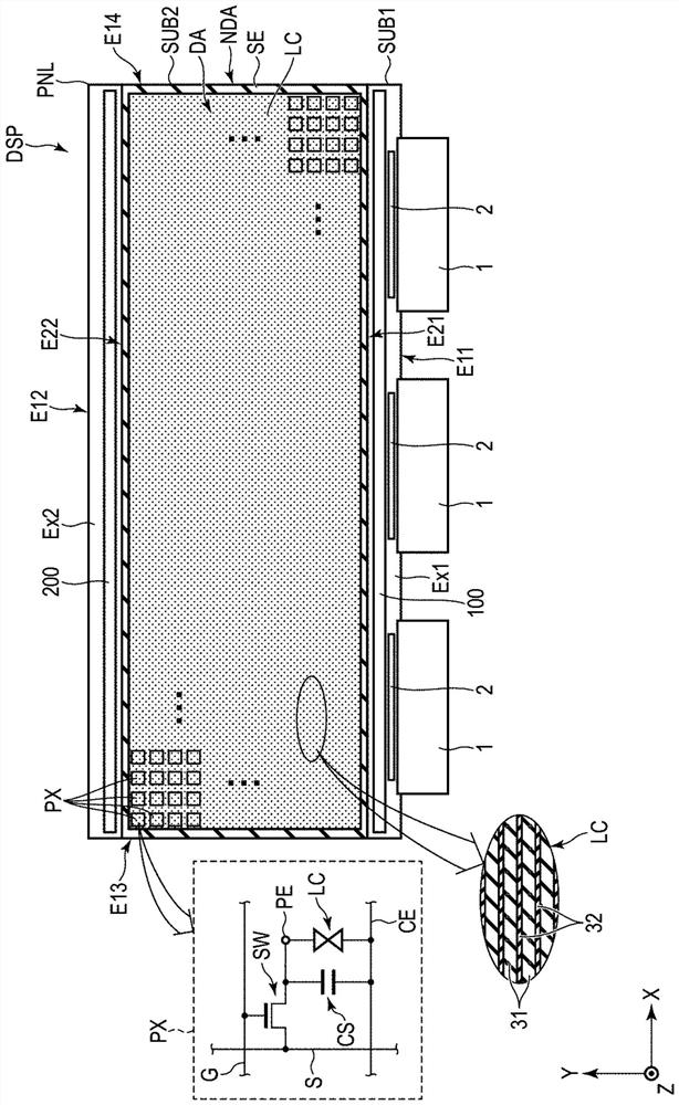
[0025] Below, while referring to the attached Figure 1 The present embodiment will be described. In addition, the disclosure is merely an example, and it is a matter of course that a person skilled in the art can easily conceive of an appropriate modification while maintaining the gist of the invention, and of course it is included in the scope of the present invention. In addition, in order to clarify the description, the drawings may schematically show the width, thickness, shape, etc. of each part compared with the actual form, but these are just examples and do not limit the interpretation of the present invention. In addition, in this specification and each figure, the same reference numerals are assigned to components that perform the same or similar functions as components described in relation to the previous figures, and overlapping detailed descriptions may be appropriately omitted.

[0026] figure 1 It is a plan view showing an example of the configuration of the...


PUM


Abstract

The purpose of the present embodiment is to provide a display device capable of suppressing a reduction in display quality. A display device according to an embodiment includes: a display panel having a first side surface extending in a first direction and having a polymer dispersed liquid crystal layer; and a first light-emitting module provided along the first side surface, the first light-emitting module comprising: a plurality of first light sources arranged in the first direction; a plurality of second light sources arranged along the first direction; the first light guide body is arranged between the plurality of first light sources and the first side surface; and a second light guide body provided between the plurality of second light sources and the first side surface, an end surface of the first light guide body and an end surface of the second light guide body facing each other with an air layer interposed therebetween.

Description

technical field [0001] Embodiments of the present invention relate to a display device. Background technique [0002] In recent years, various lighting devices including a light modulation element exhibiting light scattering or transparency have been proposed. In one example, the light modulation element includes a polymer-dispersed liquid crystal layer as the light modulation layer. The light modulation element is disposed behind the light guide plate, and scatters light incident from the side of the light guide plate. [0003] The light emitted from the plurality of light emitting elements arranged at intervals propagates inside the light guide plate while being diffused. In the vicinity of the light-emitting elements in the light guide plate, the lights from the respective light-emitting elements may not sufficiently mix with each other. In this case, there is a possibility that the brightness and darkness of light may be visually recognized as stripe-like unevenness. ...

Claims


Application Information

Patent Timeline
Patent Type & Authority Applications(China)
IPC IPC(8): G02F1/13357G02B6/00
CPCG02F1/1336G02B6/0078G02B6/0068G02B6/0058G02F1/133616G02F2202/28G02F1/1334G02F1/134309
Inventor 苟正祎奥山健太郎川上久德
Owner JAPAN DISPLAY INC
Why Eureka
Try Eureka