Displaying device and its driving method

A technology for a display device and a control device, applied in the directions of identification devices, static indicators, optics, etc., can solve problems such as inability to remedy line defects, and achieve the effect of preventing delay and attenuation, and preventing the decline of display quality.

Inactive Publication Date: 2005-06-08
SHARP KK
View PDF1 Cites 0 Cited by
  • Summary
  • Abstract
  • Description
  • Claims
  • Application Information

AI Technical Summary

Problems solved by technology

For this reason, if two or more of the multiple source lines 110 driven by one source driver are disconnected, all line defects cannot be remedied.

Method used


Image

  • Displaying device and its driving method
  • Displaying device and its driving method
  • Displaying device and its driving method

Examples


Embodiment approach 2

[0067] Refer to the following Figure 4 Another embodiment of the present invention will be described. Here, for convenience of description, devices having the same functions as those shown in the above-mentioned embodiments are assigned the same symbols, and their descriptions are omitted.

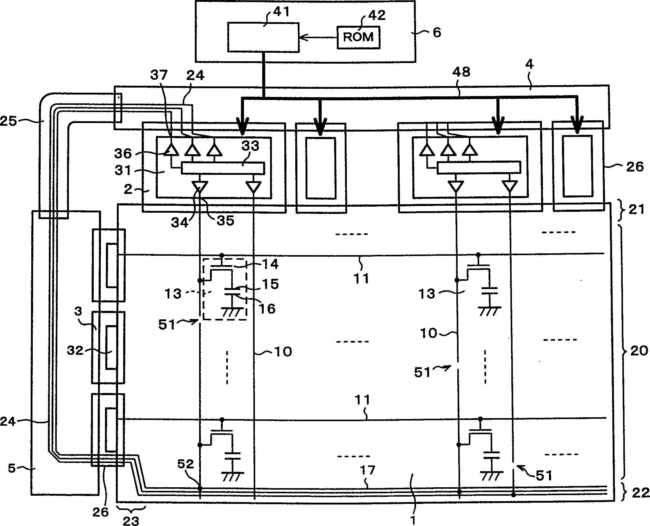
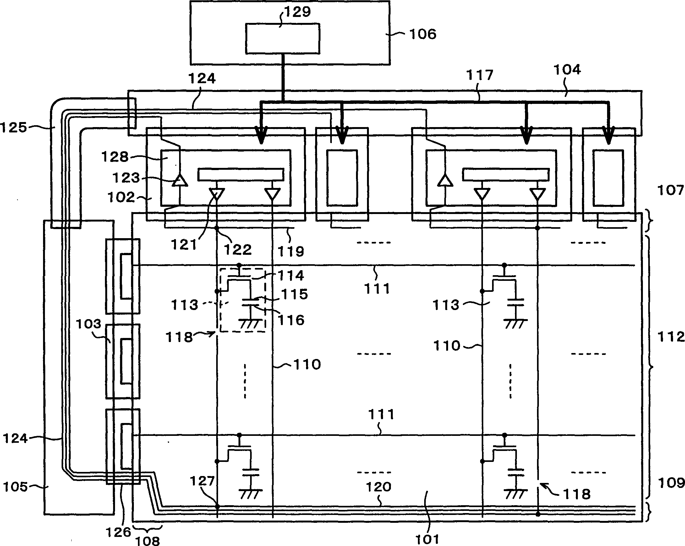
[0068] The display device of this embodiment has a structure without a gate substrate. In this structure without a gate substrate, a gate control signal from the controller 41 is supplied to the gate driver (gate TAB) 3 via the source driver (source TAB) 2 and the wiring portion 62 on the panel. Instead, the above-mentioned gate substrate 5 is eliminated. Due to the adoption of the gate-substrate-less structure, in the display device of the present embodiment, the spare lines 17 are arranged at the peripheral portion of the display area of ​​the display panel 61 .

[0069] At this time, the spare line 17 can be wired on the same path as the supply line of the above-mentioned gate contr...


PUM


Abstract

The present invention provides a display device, comprising: a plurality of gate lines and a plurality of source lines arranged in a matrix; A line for compensation connected to a broken source line with a broken line; a normal output section for supplying a display data signal to the source line and a line for supplying a display data signal to a spare line provided on the side of the source line terminal area A source driver of the compensation output unit; a controller board for controlling the source driver so that the compensation output unit outputs a data signal corresponding to a disconnected source line. In this way, in a display device having a source line capable of compensating for disconnection, by reducing the number of spare lines, the edge area can be reduced, further miniaturization can be achieved, and at the same time, the intersection of the spare line and the source line terminal area can be eliminated. The cross-capacitance suppresses the degradation of display quality.

Description

technical field [0001] The present invention relates to a display device having a compensating line for a disconnected source line and a driving method thereof. Background technique [0002] Previously, in a liquid crystal display device in which a plurality of gate lines and a plurality of source lines (signal lines) are arranged in a matrix, for example, as shown in JP-A-8-171081 (publication date: July 2, 1996) , has a structure for compensating the source line after disconnection. Next, use image 3 The structure of the liquid crystal module of this liquid crystal display device will be described. [0003] As shown in the figure, the liquid crystal display device includes a liquid crystal panel 101 , a source driver 102 , a gate driver 103 , a source substrate 104 , a gate substrate 105 , and a control substrate 106 . [0004] In the liquid crystal panel 101 , a plurality of source lines 110 and a plurality of gate lines 111 are arranged in a matrix, and pixel portions...

Claims


Application Information

Patent Timeline
Patent Type & Authority Patents(China)
IPC IPC(8): G02F1/1345G09F9/30G09G3/20G09G3/36G02F1/1343
CPCG02F1/13452G09G3/3648G09G3/3688G09G2330/08G02F1/136263G09G3/36
Inventor 白石泰
Owner SHARP KK
Why Eureka
Try Eureka