Method for producing electrophoretic display device

A technology of electrophoretic display and manufacturing method, which is applied in the directions of instruments, optics, nonlinear optics, etc., which can solve the problems of display quality reduction and adhesive entry, etc., and achieve the effect of low cost and low manufacturing

Inactive Publication Date: 2012-10-10
DAI NIPPON PRINTING CO LTD
View PDF6 Cites 0 Cited by
  • Summary
  • Abstract
  • Description
  • Claims
  • Application Information

AI Technical Summary

Problems solved by technology

Furthermore, it was found that the solvent of the adhesive would evaporate into the cell area or the pixel area other than the desired application position, thereby degrading the display quality.

Method used


Image

  • Method for producing electrophoretic display device
  • Method for producing electrophoretic display device
  • Method for producing electrophoretic display device

Examples


Embodiment Construction

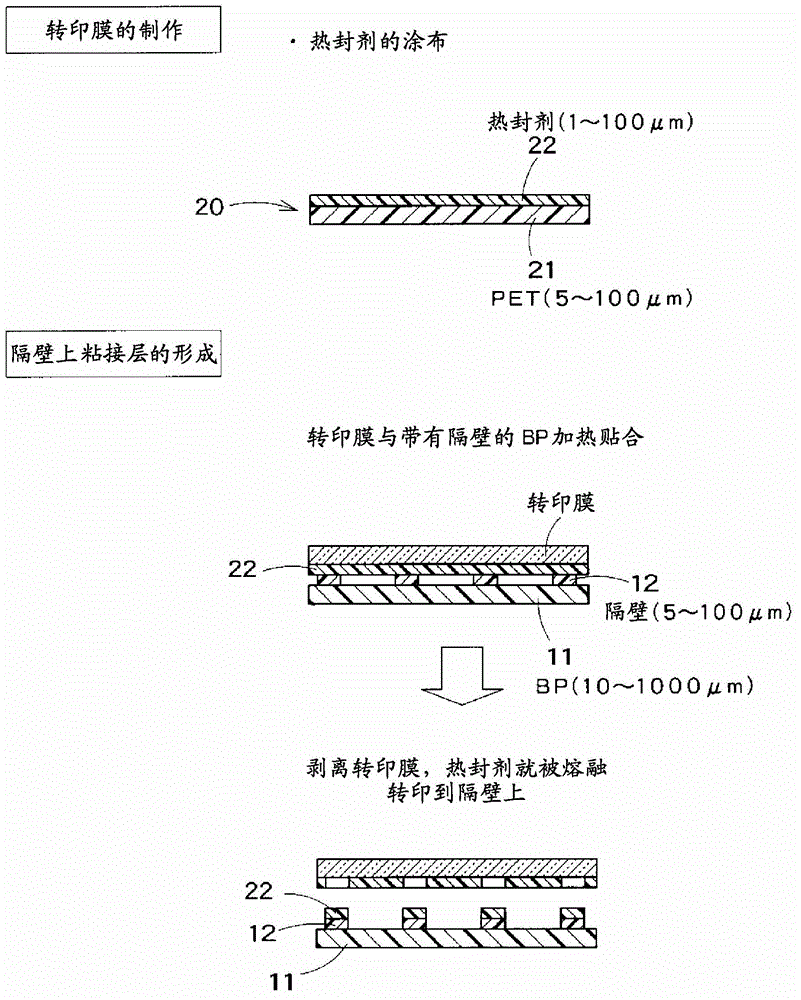
[0031] figure 1 It is a figure schematically showing the first half process of the manufacturing method of the electrophoretic display device which concerns on one Embodiment of this invention. Such as figure 1 As shown, first, by using, for example, photolithography, the upper surface of the lower substrate 11 (one substrate: base base (BP)) placed generally in the horizontal direction undergoes exposure by ultraviolet (UV) irradiation→development→ Baking is performed to form partition walls 12 in a predetermined pattern (partition rib forming step). The partition wall 12 is a member that defines the bottom and side surfaces of a plurality of cells described later.

[0032] The thickness of the partition wall is 5 to 100 μm, preferably 10 to 50 μm.

[0033] Then, an adhesive layer is formed on the partition walls 12 (adhesive layer forming step). figure 2It is a figure which schematically shows an example of an adhesive layer formation process. exist figure 2 In the a...


PUM

PropertyMeasurementUnit
melting pointaaaaaaaaaa

Abstract

The disclosed method is provided with: a partition-forming step for forming partitions on a first substrate in a predetermined pattern in order to establish each bottom surface and each side surface of a plurality of cells; an adhesion-layer-forming step for forming an adhesion layer on the aforementioned partitions; a display-medium-filling step for filling each region partitioned by the aforementioned partitions with a display medium after the aforementioned adhesion layer has been formed; and an other-substrate-adhesion step for establishing the top surface of each of the aforementioned plurality of cells and sealing off the aforementioned display medium by means of adhering another substrate onto the aforementioned adhesion layer on the aforementioned partitions. The aforementioned adhesion-layer-forming step is performed by heat-transferring a heat sealing agent using a transfer film to which said heat sealing agent has been coated. The aforementioned other-substrate-adhesion step is a heating step that obtains adhesive force by re-melting the aforementioned heat sealing agent that had been transferred as the adhesive layer.

Description

technical field [0001] The present invention relates to a manufacturing method for manufacturing an electrophoretic display device used in electronic paper and the like. Background technique [0002] An electrophoretic display device is a device that displays information by utilizing electrophoresis, that is, movement of particles, of electrophoretic bodies (usually electrophoretic particles) in the air or in a solvent. Usually, it is configured such that the state of electrophoresis is controlled by applying an electric field between two substrates, thereby realizing a desired display. [0003] In recent years, the electrophoretic display device has attracted people's attention especially as an application of electronic paper. When applied as electronic paper, the following advantages can be enjoyed: visibility at the printed matter level (easy to see with the eyes), ease of rewriting information, low power consumption, and light weight. [0004] However, electrophoretic ...

Claims


Application Information

Patent Timeline
Patent Type & Authority Applications(China)
IPC IPC(8): G02F1/167G02F1/1679
CPCG02F2001/1672G02F1/167G02F2202/28G02F1/1681Y10T29/49002Y10T29/5313G02F1/1679
Inventor 池上佳奈森住大悟
Owner DAI NIPPON PRINTING CO LTD
Why Eureka
Try Eureka