
Multimode receiver

A radio receiver, operation mode technology, applied in the circuit field, can solve the problems of direct conversion, lack of flexibility in receiver mode, unchangeable receiver operation mode, etc.

Inactive Publication Date: 2008-10-01
TOUMAZ TECH
View PDF6 Cites 0 Cited by
  • Summary
  • Abstract
  • Description
  • Claims
  • Application Information

AI Technical Summary

Problems solved by technology

Also, although the signal channel sidebands overlap in the I and Q paths, the signal is actually interfered by itself, so the 'interfering signal' power is the same as the 'desired' power
However, a major disadvantage is that any low frequency noise and offset present in the receiver will directly degrade the desired signal channel since it is centered around zero
[0012] The main drawback of the low IF receiver architecture compared to the zero IF receiver architecture is that in zero IF the interfering signal is the desired channel itself whereas in low IF the interfering signal is some other channel
Although filters and LNAs can be selected for different broadcasting standards, the receiver has the disadvantage that the operating mode of the receiver is not changeable, as dictated by the receiver structure, i.e. the operating mode is always a direct changeover
While filters can be selected for different broadcast standards, the mode of operation of the receiver is inherently fixed (i.e. superheterodyne) as dictated by its architecture
[0017] Lack of flexibility in receiver mode is the main drawback
In wireless communication receivers, for example, direct conversion may provide a compact and low-power solution for reception of wideband signals such as WCDMA, but direct conversion may not be suitable for reception of narrowband GSM signals
[0018] A second disadvantage of the prior art is that there is some redundancy in the silicon area due to the need for multiple versions of a given circuit block, i.e. the receiver of WO02 / 27953A12 requires multiple low noise amplifiers and filters, the receiver of EP1006669A1 machine requires multiple filters

Method used


Image

  • Multimode receiver
  • Multimode receiver
  • Multimode receiver

Examples


Embodiment Construction

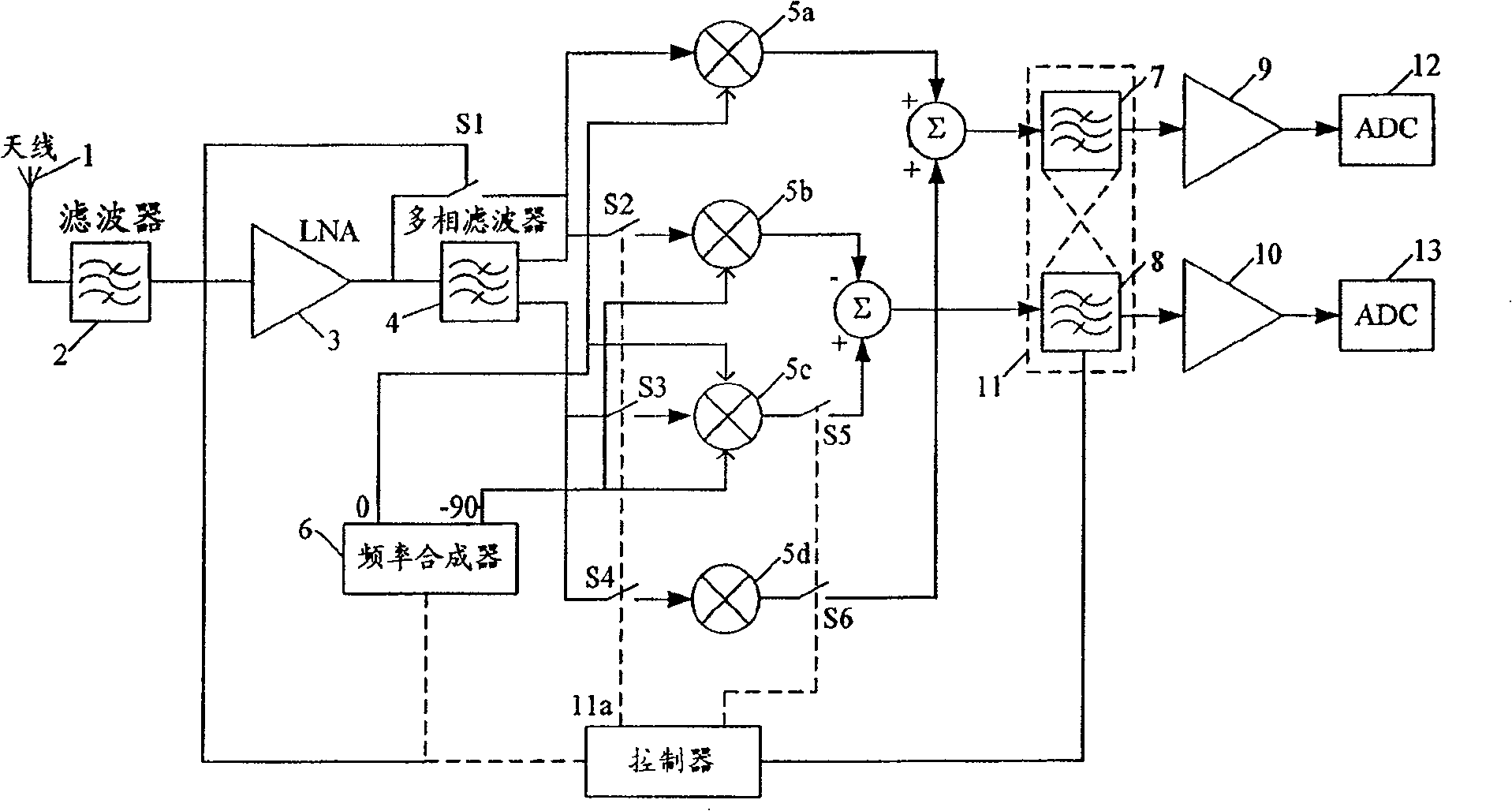
[0050] A radio receiver embodying the invention such as figure 1 shown. The reconfigurable receiver includes an antenna 1 , a bandpass filter 2 and a low noise amplifier (LNA) 3 . These common elements are connected to a radio frequency (RF) quadrature generator 4 and mixers 5a, 5b, 5c, 5d, in this embodiment the radio frequency quadrature generator 4 is shown as a passive polyphase filter, mixing The frequency converter is provided by the synthesizer 6 to mix the frequency. The outputs of the quadrature mixers 5a-5d are summed as shown, passed to baseband filters 7, 8, and from there to amplifiers 9, 10 and analog-to-digital converter (ADC) 12 , 13. As described below, the baseband filters 7, 8 may be interconnected and for ease of reference may be referred to as one entity: the baseband filter 11, as shown in box 11.

[0051] The controller 11a is connected to the frequency synthesizer 6, and sets the local oscillator (LO) frequency generated by the synthesizer. The con...


PUM


Abstract

An electric circuit suitable for use as a radio receiver or part of a radio receiver, the electric circuit comprising amplification means, frequency mixer means, and filter means, wherein the frequency mixer mans is configurable to down-convert a wanted component of the amplified input signal to one of at least two intermediate frequency bands, and the filter means is dynamically reconfigurable between a first filter configuration which provides a first operating mode, and a second filter configuration which provides a second operating mode.

Description

technical field [0001] The invention relates to a circuit suitable for use as or as part of a radio receiver. Background technique [0002] With the specific needs of different applications, there has been a rapid expansion of standards and modulation techniques for wireless communication. These modulation schemes range from simple amplitude modulation (AM) and frequency modulation (FM) to complex multicarrier digital modulation schemes such as Wideband Code Division Multiple Access (WCDMA) and Coded Orthogonal Frequency Domain Multiplexing (COFDM). This rapid expansion of standards has led to the development of many different receiver structures optimized for specific applications. [0003] A modern wireless communication receiver typically has two main sections: an analog front end and a digital back end. The digital backend performs functions such as demodulation, decoding, error correction, etc. The analog front end typically down-converts a particular desired channel...

Claims


Application Information

Patent Timeline
IPC IPC(8): H04B1/30H04B1/26
CPCH04B1/30H04B1/26H03H11/0444H03H2011/0494H03H11/04
Inventor 艾莉森·普尔太特
Owner TOUMAZ TECH
Learn More